You will have a voltage at the output at turn on, it should settle down once its all warmed up.
Sounds like its getting there.
WD phono/PSU III clone
#362
Ive never really left it running for very long to see if the voltage settles and maybe even dissapears.
Ill have a long listen and measure the outputs again after half hour or so.
I ordered some 39.2k and 316k resistors from WD. Ill get some metal films and some new bases and go from there.
There is light at the end of the tunnel
Unfortunately, poeple have put the idea of a modified EAR phono using air vane capacitors in my head
Im trying to avoid it, but i already have most of the parts. A few resistors and a couple of caps and....
#363
Best modification you can make to a EAR phono stage is to put a "for sale on ebay" sign on it (IMHO).Unfortunately, poeple have put the idea of a modified EAR phono using air vane capacitors in my head
Whenever an honest man discovers that he's mistaken, he will either cease to be mistaken or he will cease to be honest.
#364
Thats what ive heard too
This is the circuit.
http://www.jogis-roehrenbude.de/Leserbr ... n-RIAA.htm
I dunno, may build it if curiosity gets the better of me
For now, i just want to listen and buy music!
Im looking forward to the practical side of building a nice chassis, im much more comfortable in that world
This is the circuit.
http://www.jogis-roehrenbude.de/Leserbr ... n-RIAA.htm
I dunno, may build it if curiosity gets the better of me
For now, i just want to listen and buy music!
Im looking forward to the practical side of building a nice chassis, im much more comfortable in that world
-
Mike H

- Amstrad Tower of Power
- Posts: 20189
- Joined: Sat Oct 04, 2008 5:38 pm
- Location: The Fens
- Contact:
#367
Oh ma gawd, you may as well build an op-amp versiongraeme wrote:This is the circuit
"And now ladies and gentlemen, will you please welcome, all the way from IC's and trannies land, slew-rate problems..."
I think you should stick with what you've got so far, actually it's virtually identical in basic principles to what I'm using at the mo and that's the best phono pre I tried so far
Graeme wrote:We have a breakthrough
etc...

Will get a bit of flapping about on the outputs, 'specially in my case due to unsteady mains (have I mentioned that before?
 ), that's why I put 250V of Zeners across V1 supply. Shuts it up a treat
Tho you've still got to sort out why the supply flaps about with nothing coming off it... duh... ?
Brass will look smart certainly, and I can't think why you shouldn't. Should be conductive enough and not magnetic.

"No matter how fast light travels it finds that the darkness has always got there first, and is waiting for it."
-
Mike H
- Amstrad Tower of Power
- Posts: 20189
- Joined: Sat Oct 04, 2008 5:38 pm
- Location: The Fens
- Contact:
#368
Doesn't like being bent about too much unless red hot, I've found that outNick wrote:I would have thought it was hard to work with?

Sawing etc. is alright tho, plus you can solder it!
"No matter how fast light travels it finds that the darkness has always got there first, and is waiting for it."
#369
Ok, i take the 'subtle  ' hint, ill leave the EAR alone
I'd seen your mention of 'zeners' in a previous post but sort of glossed over it as i didnt understand
Ill scope the PSU on its own again and see if the new choke solved that or not.
As for the brass, i only planned on using it for the sides, aluminium for the top and probably aluminium for the base too.
-
Mike H
- Amstrad Tower of Power
- Posts: 20189
- Joined: Sat Oct 04, 2008 5:38 pm
- Location: The Fens
- Contact:
#370
Yes sorry if it seemed like I was jumping on you like that, it was the sudden shock, you know 
Is this going to be like thick brass and all polished up? That'd be cool.
Is this going to be like thick brass and all polished up? That'd be cool.
"No matter how fast light travels it finds that the darkness has always got there first, and is waiting for it."
#371
Hmm, im going to give my idea away here arent i
I plan on using vertical copper pipe at each corner, these will double as feet and have some kind of isolation built in to keep vibrations away from the valves. brass sides (shallow channel) silver soldered to the copper uprights and an aluminium top and bottom, screwed to the brass channel sides.
I dont really want a big box that will enclose the valves so i was going to chassis mount the sockets and use screening cans on the valves.
Need a capacitor mount too, where sells them?
I have access to oxy accetelene so heating/bending the brass channel wont be a problem.
I did consider reversing the front brass channel so there is a recess in the front, then enameling it, maybe with some patterned silver inlay, but i think that may be going a little too far.
Ill stick with something that looks a little 'steam punk'. Ill let the brass and copper age as it wishes.
So, what the hell are zeners?
Also, are there any upgrades worth doing to the PSU? I only ask as i believe WD now use diodes instead of a bridge rectifier for the heaters and i know people upgrade the diodes in the Hv side.
Im hoping to only do the final build once but with easily swappable caps should i wish to experiment, dont want to be ripping it apart all the time as things tend to get messy
-
Mike H
- Amstrad Tower of Power
- Posts: 20189
- Joined: Sat Oct 04, 2008 5:38 pm
- Location: The Fens
- Contact:
#372
Gordonus Bennettus...Graeme wrote:Hmm, im going to give my idea away here arent i
I plan on using vertical copper pipe at each corner, <snip>

A capacitor mounting clip do you mean? RS do...Need a capacitor mount too, where sells them?
http://uk.rs-online.com/web/search/sear ... citor+clip
http://en.wikipedia.org/wiki/Zener_diodeSo, what the hell are zeners?
"No matter how fast light travels it finds that the darkness has always got there first, and is waiting for it."
#374
Thems the things, didnt think about checking RS.
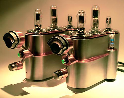
Nick, those amps are lovely! They would fit in our 50's theme, very 'atomic'.
Im sure ive seen some of his stuff before.
Interesting on the zeners. Ill read some more. I only just got my head around resistors and caps (well, just!) diodes are a step too far for me at the moment
Nick, those amps are lovely! They would fit in our 50's theme, very 'atomic'.
Im sure ive seen some of his stuff before.
Interesting on the zeners. Ill read some more. I only just got my head around resistors and caps (well, just!) diodes are a step too far for me at the moment
#375
Ok, this bit makes sense.
'Zener diodes are widely used to regulate the voltage across a circuit. When connected in parallel with a variable voltage source so that it is reverse biased, a Zener diode conducts when the voltage reaches the diode's reverse breakdown voltage. From that point it keeps the voltage at that value.'
along with this basic diagram
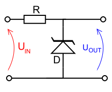
So, the zeners are placed between the Hv to V1 and 0v. When the voltage exceeds the diodes limit it shunts the rest to 0v right?
So, where to place them. between c12/13 and r19/20? connected back to the circuits 0v.
Just match the zeners breakdown voltage to the voltage we want. I guess it helps if the voltage we want is slightly below the voltage we have otherwise voltage could drop but not rise, and we want it rock steady.
Is the diodes nominal voltage its breakdown voltage?
So, if for arguments sake we want a steady 130v and we fit 130v zener it would require us to have a fluctuating voltage of say 131-132v then it always satys at 130v. If we want 130v but our voltage fluctuates from 129-131 then 130v zener would reduce the fluctuation to 129-130. If we fitted 128v of diode we'd have a steady voltage just a tiny bit too low.
They can be grouped in series to get the right voltage cant they.
Im not 100% sure if im getting this properly, i may be giving you a good laugh here
Assuming im on the right track here.
Why just use then for the voltage to V1, why not nip it in the bud earlier and fit zeners in the PSU somewhere so the whole phono has steady voltage?
'Zener diodes are widely used to regulate the voltage across a circuit. When connected in parallel with a variable voltage source so that it is reverse biased, a Zener diode conducts when the voltage reaches the diode's reverse breakdown voltage. From that point it keeps the voltage at that value.'
along with this basic diagram
So, the zeners are placed between the Hv to V1 and 0v. When the voltage exceeds the diodes limit it shunts the rest to 0v right?
So, where to place them. between c12/13 and r19/20? connected back to the circuits 0v.
Just match the zeners breakdown voltage to the voltage we want. I guess it helps if the voltage we want is slightly below the voltage we have otherwise voltage could drop but not rise, and we want it rock steady.
Is the diodes nominal voltage its breakdown voltage?
So, if for arguments sake we want a steady 130v and we fit 130v zener it would require us to have a fluctuating voltage of say 131-132v then it always satys at 130v. If we want 130v but our voltage fluctuates from 129-131 then 130v zener would reduce the fluctuation to 129-130. If we fitted 128v of diode we'd have a steady voltage just a tiny bit too low.
They can be grouped in series to get the right voltage cant they.
Im not 100% sure if im getting this properly, i may be giving you a good laugh here
Assuming im on the right track here.
Why just use then for the voltage to V1, why not nip it in the bud earlier and fit zeners in the PSU somewhere so the whole phono has steady voltage?