Ive scribbled some unused core stats and we are OK there is 76 watts of unused core. So we are only using .623% of the core capacity. So using the full ht winding bridge rectified we can divide 70mA by .623 and we get 112mA capacity. El84’s require 70mA, 6J5’s 20mA 56’s 12mA add sum = 102mA 102/112 % = 91%.
We have a choke input power supply at every stage, as the 650v supply is choke input too. Bearing in mind the 56 heaters are not coming from this core.
GM70 Amplifier
-
Paul Barker

- Social Sevices have been notified
- Posts: 8998
- Joined: Mon May 21, 2007 9:42 pm
#76 Re: GM70 Amplifier
"Two things are infinite, the universe and human stupidity, and I am not yet completely sure about the universe." – Albert Einstein
-
Mike H

- Amstrad Tower of Power
- Posts: 20189
- Joined: Sat Oct 04, 2008 5:38 pm
- Location: The Fens
- Contact:
#77 Re: GM70 Amplifier
Occurred to me too. But then I thought, maybe in the original equipment it was made for, it was for a specific thing or circuit. I was just intrigued.Paul Barker wrote: ↑Sun Dec 24, 2023 8:03 am g to h Calib. Where you connect youre probes to check calibration?
"No matter how fast light travels it finds that the darkness has always got there first, and is waiting for it."
#78 Re: GM70 Amplifier
Yep like Paul I think it's likely a 50hz source to provide on the front panel for timebase calibration.
Whenever an honest man discovers that he's mistaken, he will either cease to be mistaken or he will cease to be honest.
-
Paul Barker
- Social Sevices have been notified
- Posts: 8998
- Joined: Mon May 21, 2007 9:42 pm
#79 Re: GM70 Amplifier
I think it would make sense now to have both power supplies off board. Both arriving on same high voltage plug in’s. Well labelled. Then there is the negative supply.
Its spreading out…..
Its spreading out…..
"Two things are infinite, the universe and human stupidity, and I am not yet completely sure about the universe." – Albert Einstein
-
Paul Barker
- Social Sevices have been notified
- Posts: 8998
- Joined: Mon May 21, 2007 9:42 pm
#80 Re: GM70 Amplifier
The filament supplies Ive taken off the main power transformer, so it only has B+ to produce which means I am just using 61% of the primary winding and core capacity. Such will allow me to shunt regulate the first and the second stage. El84 probably not, signal amplitude has reached max by then.
So Im trying something new for me.
Ordered two transformers for each of 3 stages which will share the ac supply in series on the primary. One transformers secondary per valve. Thus rendering secondary in each of the 6 transformers half the rated voltage. These should not take much space neither add much weight.

The output valves are heated by Lenovo 20v laptob supplies rated at twice the current the GM70’s require thanks to Andrew Ivimey
So Im trying something new for me.
Ordered two transformers for each of 3 stages which will share the ac supply in series on the primary. One transformers secondary per valve. Thus rendering secondary in each of the 6 transformers half the rated voltage. These should not take much space neither add much weight.
The output valves are heated by Lenovo 20v laptob supplies rated at twice the current the GM70’s require thanks to Andrew Ivimey
"Two things are infinite, the universe and human stupidity, and I am not yet completely sure about the universe." – Albert Einstein
-
Paul Barker
- Social Sevices have been notified
- Posts: 8998
- Joined: Mon May 21, 2007 9:42 pm
#81 Re: GM70 Amplifier
Now I can hear Phil the scrambler on bikes from before 1965. So lets have a little rethink about what to combine and what to separate.
If I split off the two humungous and heavy Tribute output transformers together with the GM70’s and the Lenovo Filament supplies. Make that an output stage. It would pair with the already built 650v b+ supply. Build it on a plate of copper brass or steal or maybe just on a cut section of that galvanised boiler combustion chamber cover on timber.
Make the preamp driver box with its power supply and heater supplies and its bias negative supply, with adjustable direct coupled biased drive as an output which drives either the gm70 output box which has Tributees and gm70’s. Or dive the existing output stage of the parallel 801a amp from the same with bias adjusted to tailor it. Using its existing 5k output transformers but now able to drive it also into A2. Barely no work to do on that, just cut a few connections on the board bypassing all the preamp circuitry.
Use the preamp Anth made me.
"Two things are infinite, the universe and human stupidity, and I am not yet completely sure about the universe." – Albert Einstein
-
pre65

- Amstrad Tower of Power
- Posts: 21400
- Joined: Wed Aug 22, 2007 11:13 pm
- Location: North Essex/Suffolk border.
#82 Re: GM70 Amplifier
Paul Barker wrote: ↑Mon Dec 25, 2023 11:08 am Now I can hear Phil the scrambler on bikes from before 1965. So lets have a little rethink about what to combine and what to separate.
The only thing necessary for the triumph of evil is for good men to do nothing.
Edmund Burke
G-Popz THE easy listening connoisseur. (Philip)
Edmund Burke
G-Popz THE easy listening connoisseur. (Philip)
-
pre65
- Amstrad Tower of Power
- Posts: 21400
- Joined: Wed Aug 22, 2007 11:13 pm
- Location: North Essex/Suffolk border.
#83 Re: GM70 Amplifier
Just a reminder what my GK71 monoblock looked like, OPT not shown.
This is top/bottom joined together. The transformer strapped on was for the GK71 heater, came from a train set.


This is top/bottom joined together. The transformer strapped on was for the GK71 heater, came from a train set.
The only thing necessary for the triumph of evil is for good men to do nothing.
Edmund Burke
G-Popz THE easy listening connoisseur. (Philip)
Edmund Burke
G-Popz THE easy listening connoisseur. (Philip)
-
Paul Barker
- Social Sevices have been notified
- Posts: 8998
- Joined: Mon May 21, 2007 9:42 pm
#84 Re: GM70 Amplifier
Awsome
"Two things are infinite, the universe and human stupidity, and I am not yet completely sure about the universe." – Albert Einstein
-
Paul Barker
- Social Sevices have been notified
- Posts: 8998
- Joined: Mon May 21, 2007 9:42 pm
#85 Re: GM70 Amplifier
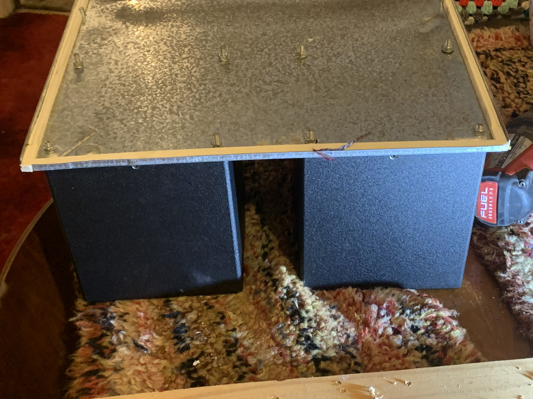
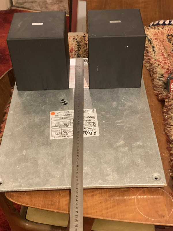
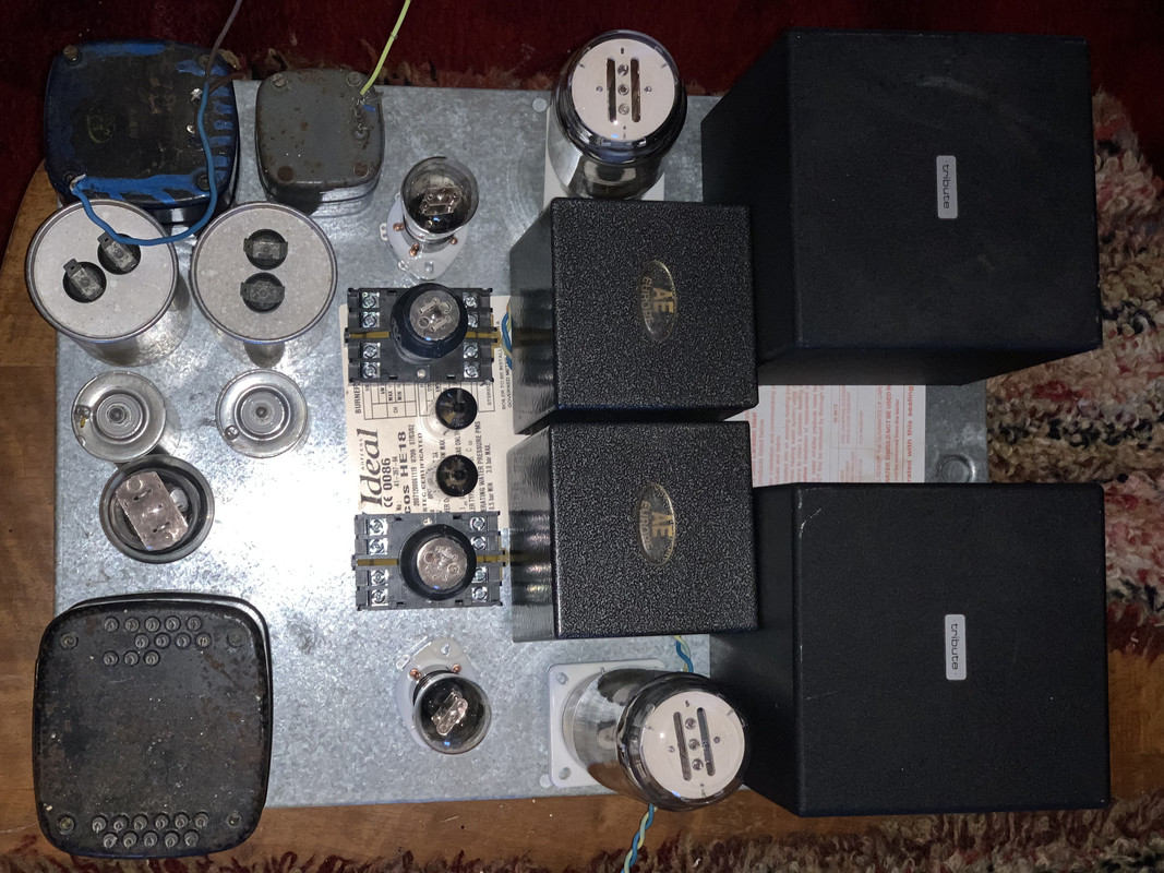
Well Ive done some laying out and mounted Output Transformers. Shown where I think Ill mount chokes and valves.
Anyone think the el84’s might get too hot?
Anyone think the el84’s might get too hot?
"Two things are infinite, the universe and human stupidity, and I am not yet completely sure about the universe." – Albert Einstein
-
Mike H
- Amstrad Tower of Power
- Posts: 20189
- Joined: Sat Oct 04, 2008 5:38 pm
- Location: The Fens
- Contact:
#86 Re: GM70 Amplifier
They are big muthas aren't they? Strewth 
"No matter how fast light travels it finds that the darkness has always got there first, and is waiting for it."
-
Paul Barker
- Social Sevices have been notified
- Posts: 8998
- Joined: Mon May 21, 2007 9:42 pm
#87 Re: GM70 Amplifier
Yes Mike the big OPT’s are a hindering all but sound quality, one hopes. But wot a booga to build.
Since Im stuck caring for Diana at home I’m looking in many directions before punching holes in the galvanised breadboard. If you noticed opts blind mounted. Ill take them off to punch one or two 20mm holes for electricians metal box grommets. Wire tails long enough passing through on final assembly. Same idea for the chokes (repurposed interstage transformers)
But my obsession with unbypassed cathode resistor got me looking at 56 again. In the vade mechum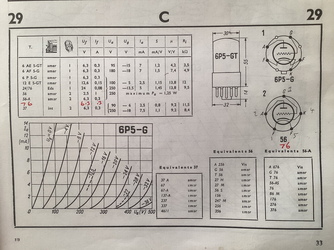
there is more info than the RCA valve guide. I have found a new operating point suggestion of 100v, which would give me an anode resistor load of 200k, but the plate resistance rises from 9.5k to 12k. The cathode bias resistor would be 2k for 5v auto bias, the load is a healthy 200kohm and assume parallel with 500kohm ( in reality this is an amorphous core grid choke beyond the measuring abilities of my inductance tester but were it 500k equivalent makes load 142kohm , I dont think Im far out there but because dc resistance miniscule compared to resistor grid leak, more linear (no leaky bias). Acording to vade mecum mu remains same ri up to 12k transconductance down from 1.45 mA/v to 1.15. So Im brought back to the suggestion of Morgan Jones that I use the higher b+ to use a high value load resistor as now the A is 10.79 which should suffice. So I get my precious local feedback. I dont actually know what mechanism is at play whether it is the feedback or whether the distortion of capacitors avoidance. Certainly if to get the low frequency pole right an electrolytic were used, S Bench has clearly demonstrated the capacitor version of bhcurve theory he demonstrated on a scope isnt linear with electrolytics. Probably no issue with pio or polyprops. But anyway avoided that hot potato. All these little increments combine. The cost is a small drop in gain, another benefit is incrementally not worrying if or how much a solid state ccs load influences distortion composition. Long way of saying should sound better. That ccs was niggling me anyway.
I did also consider battery cathode bias. But to be fair Ive never particularly noticed improvement there, though friend Stephie showed higher odd distortions are found in capacitor bypass. I have clearly heard battery bias more dull than unbypassed resistor. So gathering all my experience over the years its unbypassed cathode bias mainly because the new operating point doesnt cripple gain.
So I guess I could now mount that valve base.
But there is a newer change. Ive found a smaller ht transformer 1200vct @110mA. So I may find I can mount the plus supply for 56/6j5/el84 with chokes and capacitors on this galvanised metal plate. So again choke input, maybe valve rectified. So looking at the piece of metal the sinal section may have a power supply section in front of it, to keep power transformer away from signal inductors and transformers. Oh boy, it wont look pretty as if it had gm70s in front, but should sound better. Lets hope. First Ill see if it all fits.
"Two things are infinite, the universe and human stupidity, and I am not yet completely sure about the universe." – Albert Einstein
-
izzy wizzy

- Old Hand
- Posts: 1496
- Joined: Fri Nov 02, 2007 7:02 pm
- Location: Auckland NZ
- Contact:
#88 Re: GM70 Amplifier
Amazing project Paul.
Fitting it in is one thing with these transmitter valve amps. Being able to move it especially when making it is another.
Are you sure a stereo chassis is a practical thing physically?
Fitting it in is one thing with these transmitter valve amps. Being able to move it especially when making it is another.
Are you sure a stereo chassis is a practical thing physically?
-
pre65
- Amstrad Tower of Power
- Posts: 21400
- Joined: Wed Aug 22, 2007 11:13 pm
- Location: North Essex/Suffolk border.
#89 Re: GM70 Amplifier
Paul is going to a gym.izzy wizzy wrote: ↑Mon Jan 01, 2024 11:47 am
Are you sure a stereo chassis is a practical thing physically?
I can just lift one monoblock on my version, but it's easier if I detach the top part first.
The only thing necessary for the triumph of evil is for good men to do nothing.
Edmund Burke
G-Popz THE easy listening connoisseur. (Philip)
Edmund Burke
G-Popz THE easy listening connoisseur. (Philip)
-
Paul Barker
- Social Sevices have been notified
- Posts: 8998
- Joined: Mon May 21, 2007 9:42 pm
#90 Re: GM70 Amplifier
I can deadlift 120kg I way 66kg so plan is achieve twice my body weight in time. My coach cant do that and only trained 3 people who can. So not a small target.
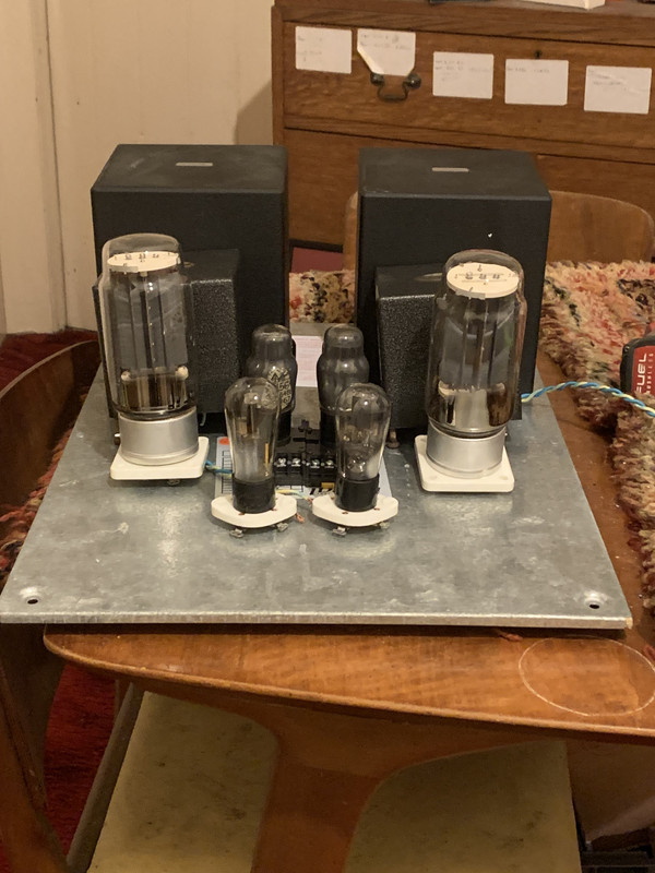
In the pictures below the main b+ 650v is off board. This is just a 110ma supply with some filametns
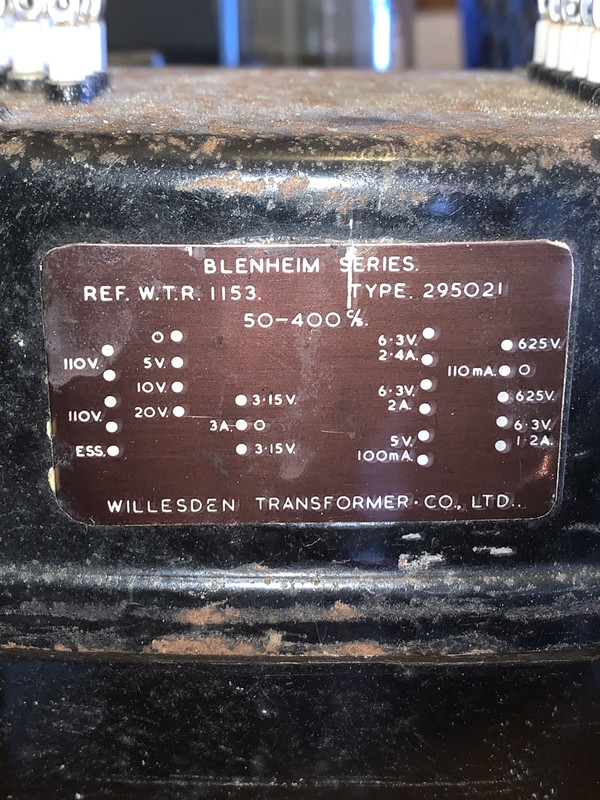
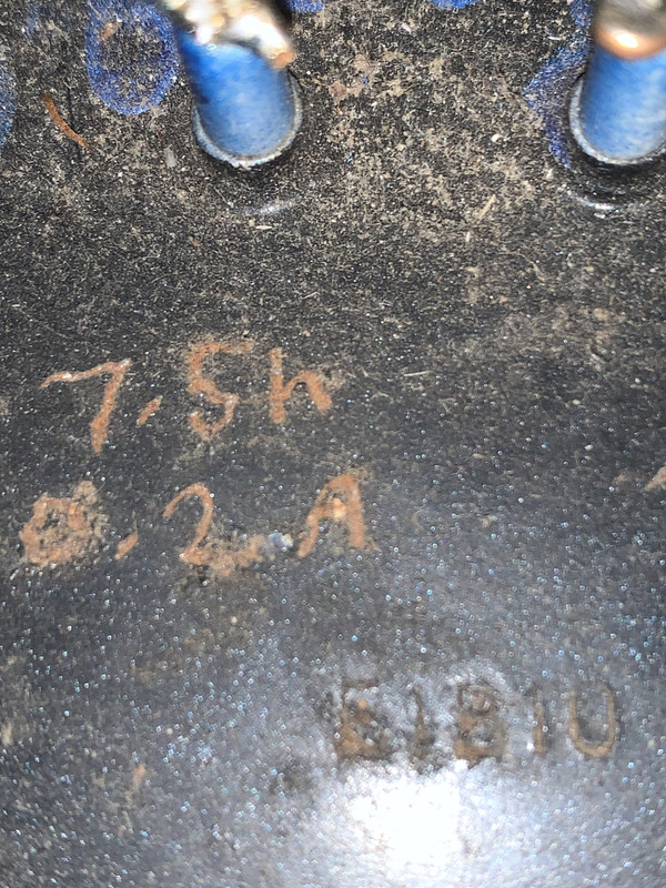

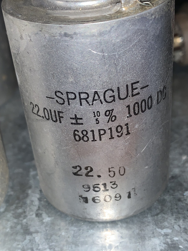
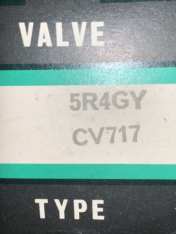
In the pictures below the main b+ 650v is off board. This is just a 110ma supply with some filametns
"Two things are infinite, the universe and human stupidity, and I am not yet completely sure about the universe." – Albert Einstein