#1 AMB linestage rebuild
Posted: Thu Jan 27, 2022 3:04 pm
Some years ago I set off for the Sunlit Uplands Of Balanced System Operation in an effort to get away from the Morlocks Of The Ground Loop. Unfortunately, along the way I fell down the Rabbit Hole Of Pin One Problems when I built a linestage that, in its effort to cater for a mixture of balanced and unbalanced sources, responds with "Que?" when asked about AES48 compliance.
Yes, yes, I know I'm a bit out on a limb here for still plugging away at this when quite a number of others are perfectly happy with RCA unbalanced and a single pot in a box (see what I did there - "plugging away" ha ha) but I'm a stubborn sod at times.
There are two VERY good articles by Bruno Putzeys of Hypex Audio which have helped me to finally understand grounding in balanced systems, and how to do it properly - The G Word, or How to Get Your Audio off the Ground and a shorter related article Dealing with legacy pin 1 problems.
The AES48 standard is actually quite simple - Pin 1 of the XLR connector has the shield connected to it, and that should be connected directly to the chassis at the socket - and nowhere else. Imagine metal box 1 connected to metal box 2 with the shield acting as a tunnel between them, inside which the circuitry and signal send/return can get on with doing what they do without a load of pesky RFI getting in on the act. The problems start when designers connect Pin 1 to circuit ground reference and to quote Bruno: "instead of shunting away circulating currents into the chassis, this actually invites them in to have an all night party, romp around in the furniture and be sick all over the carpet".
In the case of my linestage, all the Pin 1's and RCA shells from the unbalanced inputs are tied together via ground planes on the input selector relay boards and floated above chassis via a 10R resistor and cap. Yuck! OK, it still works pretty well, but I'm convinced it could be made to work even better. So I've decided to substantially re-do it - the treatment of Pin 1 is classically wrong, the signal paths from the input sockets are all longer than they should be and are a complete rats nest, there are too many Molex board-to-board connectors in the signal path for my liking, and I want a clearly labelled manual source select switch instead of having to rely on the remote. Meredith is always asking me how to switch it back to TV when I've been listening to records.
Bruno also publishes a circuit for an active linestage in The G Word which is quite similar to my a24 in that it starts with an instrumentation amplifier, but then takes a very elegant approach to adjusting the volume by putting the variable resistance in the feedback loop of one of the following inverting amplifier stages, rather than the usual method of treating the attenuator as a separate entity - you no longer need 4 perfectly matched gangs of adjustment (which doesn't exist). The original version used a linear carbon-track pot and adjustment could be fiddly at the low end, and there was a danger at the high end that the stage gain could go to infinity if the dial was twisted far enough. There was another hazard, the wiper losing contact with the track could also result in a speaker-destroying jolt.
There are several long threads on diyaudio covering the design, people's experience with it, and ways to make it more user-friendly. One of the more popular solutions was Hans Polak's relay board which could be wired in place of the pot to give a 63dB range of adjustment in 1dB steps. Jürgen Herrmann has taken this a step further with a PCB that replicates the circuit with my favoured OPA1612 op-amps (as used in the AMB a24) and integrates the relays onto the same circuit board. Even better, he published the design in KiCad, my PCB editor of choice, so I'm able to make my own modifications to it. This is what I shall use. One such mod is taking out all the power supply gubbins I don't need, as I intend to re-use the excellent AMB sigma 22 dual-rail supply that I already have.
The other one is to change to latching relays per the AMB boards, this way I can build up matching driver boards. With the relays switching in the same R-2R pattern as my current AMB delta1 boards, I should then be able to stick with the existing AMB / LCDuino / Arduino control ecosystem with minimal software changes. I'll be designing my own input selection PCB to handle balanced source switching on one board, the output of which will be fed to the integrated volume control / linestage board. The I/O will be simplified to 5 inputs, one output, no RCA connectors, everything wired to be compliant with AES48. I will make up special RCA to XLR cables for unbalanced sources per Bruno's tips in his related article.
On the front panel, the VU meters are going away, as they really don't work for me. They either barely move if we're listening at quiet levels, or crash against their end stops if we're watching a movie with lots of explosions in it (one of the needles fell off during a particularly loud one). The incandescent bulbs that illuminate them keep going black and blowing all the time as well. They will be repurposed, along with the a24 boards, into a small buffer circuit for feeding analogue signals into the computer, where they'll actually be useful for level setting. I'll probably use one of the spare silent switcher boards for this, then it can be powered from a USB port.
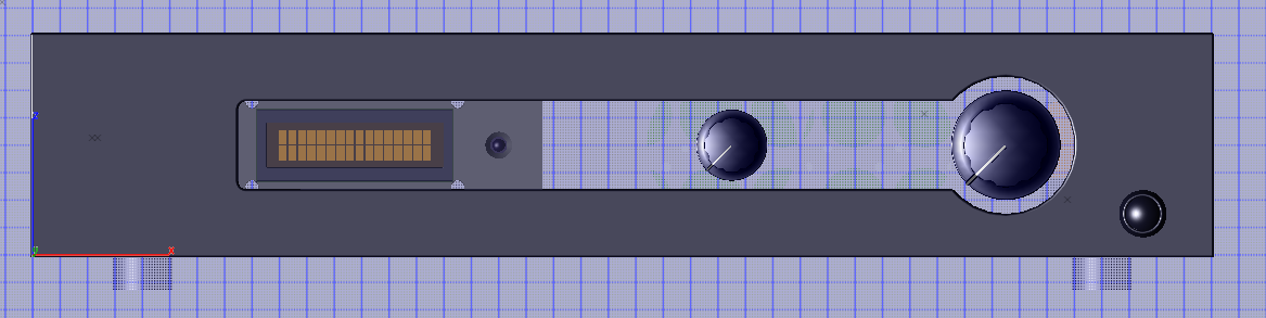
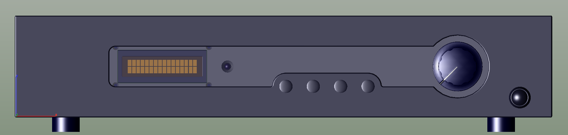
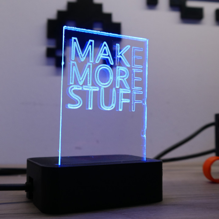
I'm currently working on a front panel redesign inspired by the Quad 34, which I find incredibly pleasing for its aesthetic and functional layout. The inner panel will be made of clear perspex and incorporate the 16x2 orange display, but extend all the way across, with control/source labelling text etched onto the back and side-lit on power-up, a bit like this. I've ordered a small piece of engraved perspex from Schaeffer as a proof of concept that I can play about with before I commit to a full size design.
Kind of a rambling intro, but watch this space. There's quite a lot of stuff to do to make this work. I still have the Millett phono stage power supply to tidy up, and there's one or two things I want to re-do on the 300B amps too.
Yes, yes, I know I'm a bit out on a limb here for still plugging away at this when quite a number of others are perfectly happy with RCA unbalanced and a single pot in a box (see what I did there - "plugging away" ha ha) but I'm a stubborn sod at times.
There are two VERY good articles by Bruno Putzeys of Hypex Audio which have helped me to finally understand grounding in balanced systems, and how to do it properly - The G Word, or How to Get Your Audio off the Ground and a shorter related article Dealing with legacy pin 1 problems.
The AES48 standard is actually quite simple - Pin 1 of the XLR connector has the shield connected to it, and that should be connected directly to the chassis at the socket - and nowhere else. Imagine metal box 1 connected to metal box 2 with the shield acting as a tunnel between them, inside which the circuitry and signal send/return can get on with doing what they do without a load of pesky RFI getting in on the act. The problems start when designers connect Pin 1 to circuit ground reference and to quote Bruno: "instead of shunting away circulating currents into the chassis, this actually invites them in to have an all night party, romp around in the furniture and be sick all over the carpet".
In the case of my linestage, all the Pin 1's and RCA shells from the unbalanced inputs are tied together via ground planes on the input selector relay boards and floated above chassis via a 10R resistor and cap. Yuck! OK, it still works pretty well, but I'm convinced it could be made to work even better. So I've decided to substantially re-do it - the treatment of Pin 1 is classically wrong, the signal paths from the input sockets are all longer than they should be and are a complete rats nest, there are too many Molex board-to-board connectors in the signal path for my liking, and I want a clearly labelled manual source select switch instead of having to rely on the remote. Meredith is always asking me how to switch it back to TV when I've been listening to records.
Bruno also publishes a circuit for an active linestage in The G Word which is quite similar to my a24 in that it starts with an instrumentation amplifier, but then takes a very elegant approach to adjusting the volume by putting the variable resistance in the feedback loop of one of the following inverting amplifier stages, rather than the usual method of treating the attenuator as a separate entity - you no longer need 4 perfectly matched gangs of adjustment (which doesn't exist). The original version used a linear carbon-track pot and adjustment could be fiddly at the low end, and there was a danger at the high end that the stage gain could go to infinity if the dial was twisted far enough. There was another hazard, the wiper losing contact with the track could also result in a speaker-destroying jolt.
There are several long threads on diyaudio covering the design, people's experience with it, and ways to make it more user-friendly. One of the more popular solutions was Hans Polak's relay board which could be wired in place of the pot to give a 63dB range of adjustment in 1dB steps. Jürgen Herrmann has taken this a step further with a PCB that replicates the circuit with my favoured OPA1612 op-amps (as used in the AMB a24) and integrates the relays onto the same circuit board. Even better, he published the design in KiCad, my PCB editor of choice, so I'm able to make my own modifications to it. This is what I shall use. One such mod is taking out all the power supply gubbins I don't need, as I intend to re-use the excellent AMB sigma 22 dual-rail supply that I already have.
The other one is to change to latching relays per the AMB boards, this way I can build up matching driver boards. With the relays switching in the same R-2R pattern as my current AMB delta1 boards, I should then be able to stick with the existing AMB / LCDuino / Arduino control ecosystem with minimal software changes. I'll be designing my own input selection PCB to handle balanced source switching on one board, the output of which will be fed to the integrated volume control / linestage board. The I/O will be simplified to 5 inputs, one output, no RCA connectors, everything wired to be compliant with AES48. I will make up special RCA to XLR cables for unbalanced sources per Bruno's tips in his related article.
On the front panel, the VU meters are going away, as they really don't work for me. They either barely move if we're listening at quiet levels, or crash against their end stops if we're watching a movie with lots of explosions in it (one of the needles fell off during a particularly loud one). The incandescent bulbs that illuminate them keep going black and blowing all the time as well. They will be repurposed, along with the a24 boards, into a small buffer circuit for feeding analogue signals into the computer, where they'll actually be useful for level setting. I'll probably use one of the spare silent switcher boards for this, then it can be powered from a USB port.
I'm currently working on a front panel redesign inspired by the Quad 34, which I find incredibly pleasing for its aesthetic and functional layout. The inner panel will be made of clear perspex and incorporate the 16x2 orange display, but extend all the way across, with control/source labelling text etched onto the back and side-lit on power-up, a bit like this. I've ordered a small piece of engraved perspex from Schaeffer as a proof of concept that I can play about with before I commit to a full size design.
Kind of a rambling intro, but watch this space. There's quite a lot of stuff to do to make this work. I still have the Millett phono stage power supply to tidy up, and there's one or two things I want to re-do on the 300B amps too.


