#1 Wright RTP3C pre-amp
Posted: Sat Mar 06, 2021 4:30 pm
Following hot on the heels of the 300B Newtons, I'm turning my attention to what sits between them and the turntable cartridge.
I want a circuit that is differential throughout, like the 300Bs, and is well regarded enough to have a good chance of replacing the Whest, which is itself a very good stage.
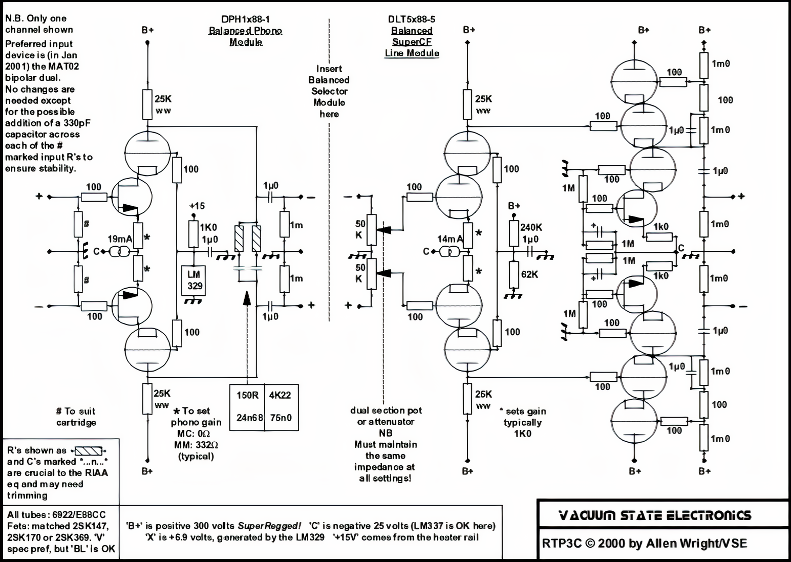
So I've given myself a bit of a challenge here - the Allen Wright-designed RTP3C. The elegance of it pleases me the same way the 300B Olson circuit does, and it seems to be very well regarded. Three differential stages from phono cartridge to low-impedance output.
My plan is to build it as two monoblocks, my hope is that doing it this way should leave room for the power supplies and remove the need to mess about with umbilicals. Yes, I know that the power supply is usually separated for this design, but there are plenty of phono stages out there that have the power supply in the same box and they work fine, I'll just have to take care with layout and grounding. Also, the fact that the LCDuino relay attenunation / source switching system I use decouples the actual relay boards from the control interface means I can monoblock it without compromising ease of operation.
Turning to the circuit, linked below. I'm toying with the idea of maybe substituting a 6C45PI in the first stage, to increase the phono stage gain a bit, although I haven't worked out yet how that will affect the RIAA response (also, oscillation risk?). And possibly a 6H30 in the output stage to lower the output impedance - I want to get that down as low as possible because of the low impedance input on the 300Bs and the long cables that run to them. Probably won't bother with the "superregs" - I'm sure Kevin Carter's shunt regulated supplies or similar will be fine.
I do have a copy of the Tube Preamp cookbook so I'll be poring over that, as well as this DIYaudio thread. Progress will likely be slow as I have other things I need to be sorting out, but I thought I'd pop this up here as a starting point. Circuit below (I cleaned this up a bit from the low-rez GIF, but the process 'filled in' the dotted lines representing the grids!). The first step will be a Spice model to see the effect of swapping out to different valves.
I want a circuit that is differential throughout, like the 300Bs, and is well regarded enough to have a good chance of replacing the Whest, which is itself a very good stage.
So I've given myself a bit of a challenge here - the Allen Wright-designed RTP3C. The elegance of it pleases me the same way the 300B Olson circuit does, and it seems to be very well regarded. Three differential stages from phono cartridge to low-impedance output.
My plan is to build it as two monoblocks, my hope is that doing it this way should leave room for the power supplies and remove the need to mess about with umbilicals. Yes, I know that the power supply is usually separated for this design, but there are plenty of phono stages out there that have the power supply in the same box and they work fine, I'll just have to take care with layout and grounding. Also, the fact that the LCDuino relay attenunation / source switching system I use decouples the actual relay boards from the control interface means I can monoblock it without compromising ease of operation.
Turning to the circuit, linked below. I'm toying with the idea of maybe substituting a 6C45PI in the first stage, to increase the phono stage gain a bit, although I haven't worked out yet how that will affect the RIAA response (also, oscillation risk?). And possibly a 6H30 in the output stage to lower the output impedance - I want to get that down as low as possible because of the low impedance input on the 300Bs and the long cables that run to them. Probably won't bother with the "superregs" - I'm sure Kevin Carter's shunt regulated supplies or similar will be fine.
I do have a copy of the Tube Preamp cookbook so I'll be poring over that, as well as this DIYaudio thread. Progress will likely be slow as I have other things I need to be sorting out, but I thought I'd pop this up here as a starting point. Circuit below (I cleaned this up a bit from the low-rez GIF, but the process 'filled in' the dotted lines representing the grids!). The first step will be a Spice model to see the effect of swapping out to different valves.