801A VT62 Power and Distortion

If they glow, this is the place to be
User avatar
Paul Barker
Social Sevices have been notified
Posts: 8836
Joined: Mon May 21, 2007 9:42 pm

#1 801A VT62 Power and Distortion

Post by Paul Barker »

All operating points chosen to kiss the 20% maximum dissipation curve.

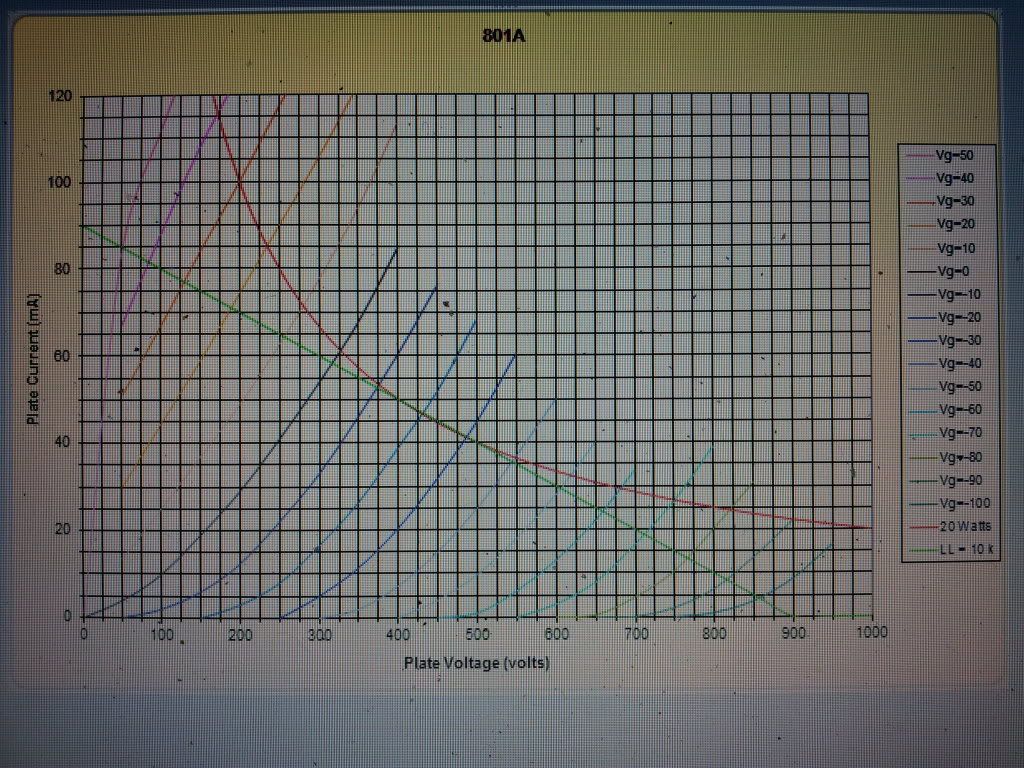
Anyone who understands characteristic curves will have spoted that for maximum power and minimum distortion we need to use high impedance load and some Class A2.

Here are two examples to demonstrate the issue.
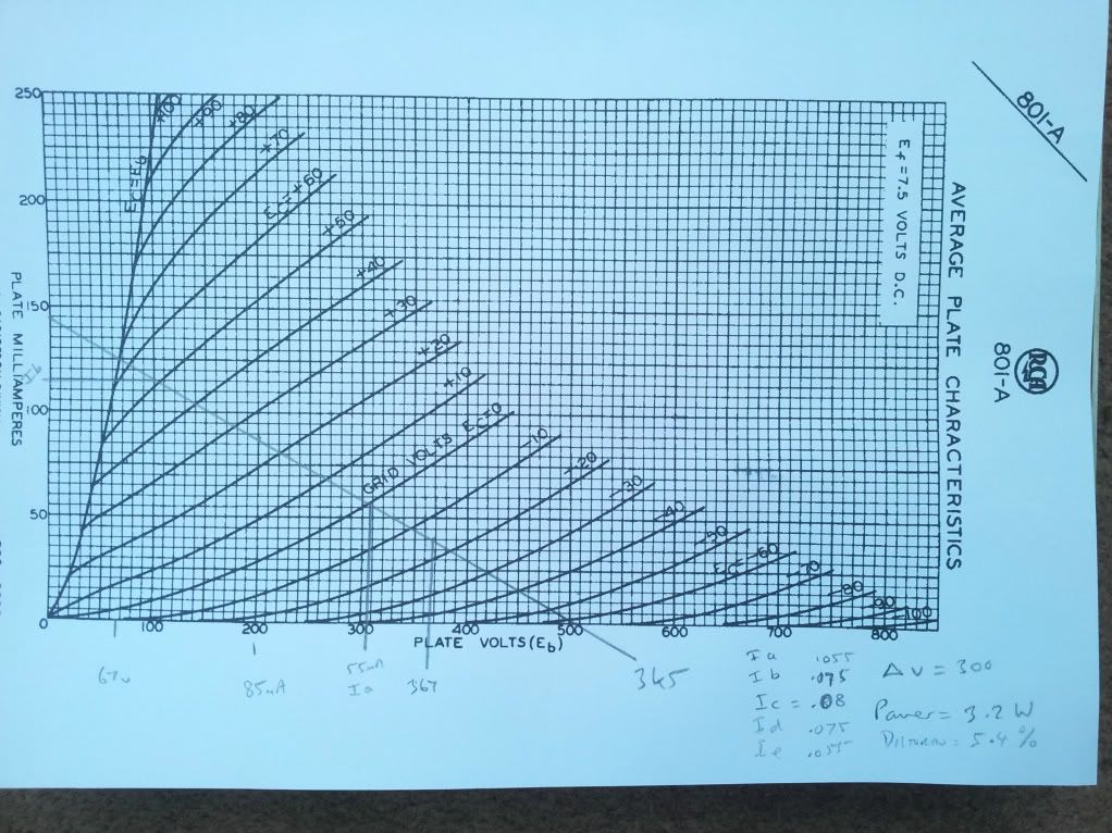
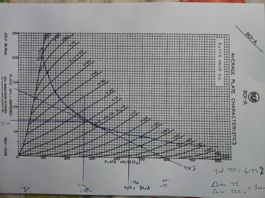
Load 4k5

Quiescent 450v -29v 0.03A


Maximum power requires +10 volts A2 drive.

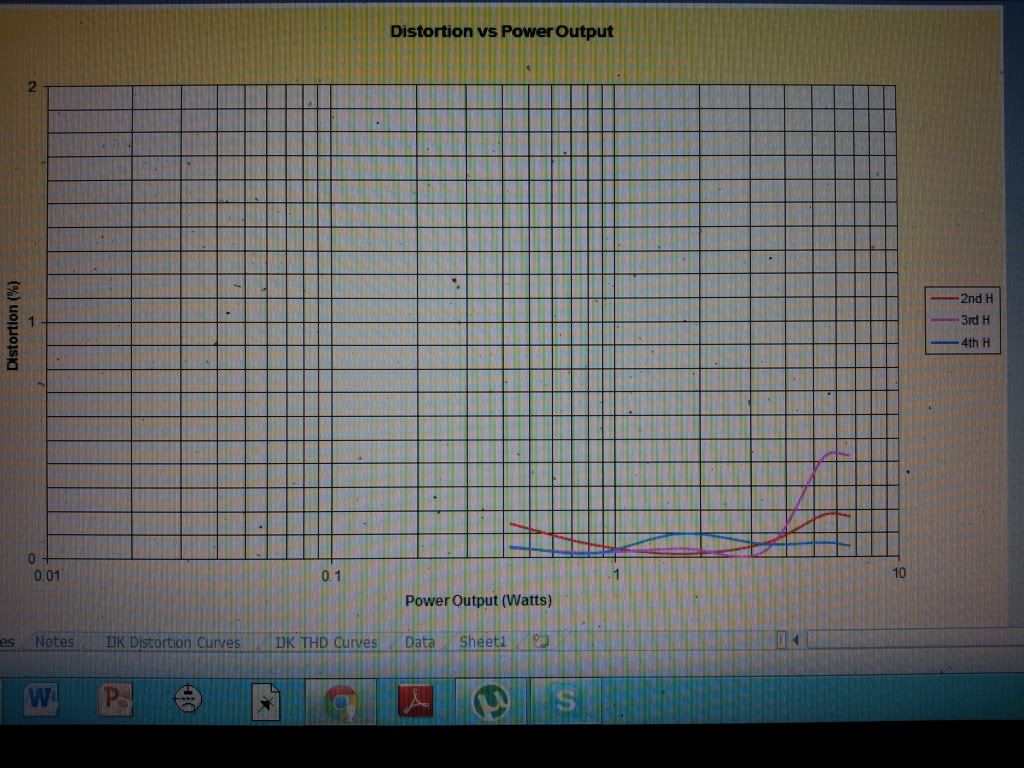
Power output 3 Watts 2nd Harmonic distortion 6.73 %

Image

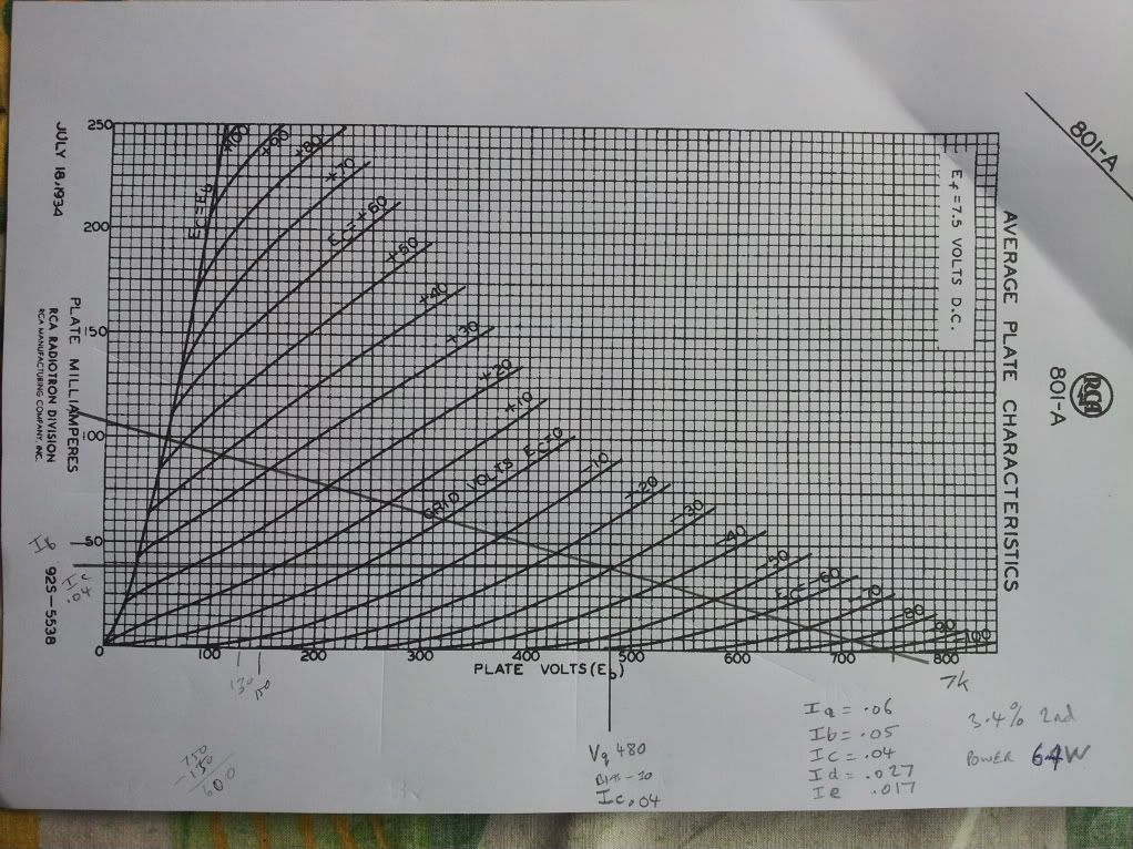
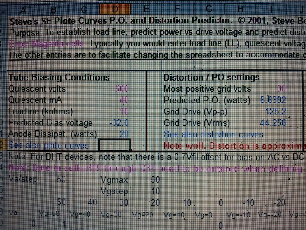
Let us see what we can do with a 7k loadline (because I have some 7k transformers) at similar sane voltages.


Quiescent 480v -30 0.04A into 7k

Maximum power requires +30v A2 drive

Power output 6.4 Watts 2nd Harmonic distortion 3.4 %

The proviso here is that in the effort to drive the grid positive 30v we don't add any distortion.

Image
User avatar
Paul Barker
Social Sevices have been notified
Posts: 8836
Joined: Mon May 21, 2007 9:42 pm

#2

Post by Paul Barker »

Obviously it is another valve which screams to be operated in Class A2.

You will have spotted that if you shift your quiescent position left along the voltage line on the 4k5 loadline so that you have to drive the grid more positive you too will achieve greater output power. I haven't worked the distortion for you at any further operating points as it is quite an excercise and I just wanted to set the stage.

What I tend to do when selecting a load from loadlines is offer up a 5% distortion rule and tilt it to reduce distortion if at all possible to 5%. It's a very simple rule of thumb technique.

From doing that with the 801 I found that over in the class A1 suggested operaing points as per the RCA Data, you cannot achieve distortion as little as 5% at any load.

Here we are only looking at 2nd Harmonic not THD. But 2nd is the dominant distortion in a DHT. We can fairly safely ignore the others, which have learned by using our ears.
Last edited by Paul Barker on Fri Apr 06, 2012 8:58 am, edited 1 time in total.
Cressy Snr
Amstrad Tower of Power
Posts: 10547
Joined: Wed May 30, 2007 12:25 am
Location: South Yorks.

#3

Post by Cressy Snr »

Here's another one

He uses an 11K loadline, but it shouldn't be that different to 10K.
It runs at Mr I's 400 odd volt sweet spot.

It is a nice article too.
http://www.diy-audio-guide.com/801a-amplifier.html
Sgt. Baker started talkin’ with a Bullhorn in his hand.
User avatar
Paul Barker
Social Sevices have been notified
Posts: 8836
Joined: Mon May 21, 2007 9:42 pm

#4 Re: 801A VT62 Power and Distortion

Post by Paul Barker »

OK thank you for another example Steve

So continuing to work with:
Paul Barker wrote:
Quiescent 480v -30 0.04A into 7k

Maximum power requires +30v A2 drive

Power output 6.4 Watts 2nd Harmonic distortion 3.4 %

The proviso here is that in the effort to drive the grid positive 30v we don't add any distortion.
What drive to do we need to achieve this?

Surprisingly little. The grid at +30v only pulls 2.76 mA. 6.4watts less than 5% distortion without having to stand on our head to design a suitable driver. Just a commonal garden direct coupled cathode follower will do.

The reason we don't have the 30mA grid current worries the writer of that article has is because (more by luck than judgement, but it has passed the test so we don't need to look further) our operating point does not require low anode voltages that take it into the area of the grid current curves which starts to curve upwards.

We have not been looking for a theoretical maximum power operating point. we have simply looked at the curves if you like as an art form, decided how we would reasonably like to see the quiescent operating point and then drawn in the factors to calculate our resulting power and distortion. If we like it we accept it. If we don't we try something else. For my 7k transformers I am happy to stop there. It happens to have the right mix of A1 and A2 that brings a suitable power and distortion without requiring some horrible mosfet driver or some expensive interstage transformer.
User avatar
Paul Barker
Social Sevices have been notified
Posts: 8836
Joined: Mon May 21, 2007 9:42 pm

#5

Post by Paul Barker »

If anyone wants a starting point example at their given output transformer situation, fire away.

It is also clear that if we go for A2 more actively we can achieve plenty of power from a 4k5 load, but were we to do that the grid would definately suck 30mA's through our driver's connection to it.

If you happen to have a step down interstage and wish to connect it so that the flux in the secondary cancels the flux in the primary (at the 30 mA) but with sufficient gap to cope when there is no secondary flux (when in A1) you are onto a winner.
User avatar
andrew Ivimey
Social Sevices have been notified
Posts: 8305
Joined: Mon Jun 11, 2007 8:33 am
Location: Bedford

#6

Post by andrew Ivimey »

I'm on my phone... Shushido does some A2 amps with PVT25, LOADS. OF POWER... 8 watts!
Philosophers have only interpreted the world - the point, however, is to change it. No it isn't ... maybe we should leave it alone for a while.
User avatar
Paul Barker
Social Sevices have been notified
Posts: 8836
Joined: Mon May 21, 2007 9:42 pm

#7

Post by Paul Barker »

Thank you for the heads up Andrew?
andrew Ivimey wrote:I'm on my phone... Shushido does some A2 amps with PVT25, LOADS. OF POWER... 8 watts!
Surprise surprise, 6EM7!

Image
Image
User avatar
Paul Barker
Social Sevices have been notified
Posts: 8836
Joined: Mon May 21, 2007 9:42 pm

#8

Post by Paul Barker »

At 200v he's proper driving it into A2!

I've run the numbers for the first schemat.

The second is close enough not to be worth bothering to run numbers again.

With the 3k5 load at 200v we get 85mA We can get a theoretical maximum voltage swing of 300v peak to peak.300 squared/8X3500 = 3.2 watts. There is no 8 watts possible at that operating point.

2nd Harmonic is 5.4% We have to power the grid with 27mA without distortion to achieve 3.2 Watts at 5.4% distortion.

Image

Note to Mark. I took this in my conservatory this morning which has West light there is a pink carpet, the cheap fluerescents were on. Normally colour correction automatic of digital cameras is better than we used to get from a cheap lab. But this looks like the prints i used to get from a rough outfit on the Isle of Dogs before they built Canary Warf. They got a horrible colour hue in eveything. I don't think they were ever this far off the mark though.

Just shows the modern digital era isn't always geting it right.
User avatar
IslandPink
Amstrad Tower of Power
Posts: 10041
Joined: Tue May 29, 2007 7:01 pm
Location: Denbigh, N.Wales

#9

Post by IslandPink »

Interesting stuff, Paul . Like you say, it's rare to trick a digital camera into that sort of colour error .
To be honest I still stick to film cameras, as there's no viable way of projecting an image from digital files to anything like the quality you get from a 35mm slide projected via a Leica slide projector. Just took two nice rolls of slide film up in the Lakes last week ( the sunny week ) . Looking forward to seeing those, conditions were stunning .
Also, no-one has yet shown me a decent black and white print from digital that equals a 20x16" fibre print from 6x9cm FP4 , they are not even close .

On the 801 in A2, there is (somewhere) a nice article by Steve Bench on driving an 801A in A2, with graphs of the distortion products as a function of power. It's not easy to find though, not on his main site, maybe it's on Intact Audio or Triode Mafia somewhere. As I remember it, he did acheive a max of 8W somehow , but the distortion products got a bit ugly, with too much 3rd and 5th harmonic , beyond 3 or 4 watts . But it's worth doing to get 2-3 watts .
"Once you find out ... the Circumstances ; then you can go out"
User avatar
Paul Barker
Social Sevices have been notified
Posts: 8836
Joined: Mon May 21, 2007 9:42 pm

#10

Post by Paul Barker »

that is helpful information.
User avatar
Paul Barker
Social Sevices have been notified
Posts: 8836
Joined: Mon May 21, 2007 9:42 pm

#11

Post by Paul Barker »

Right Mark's information bore very effective fruit.

I have taken a screen shot of my operating point and my predictions which I arrived at just by ruler pencil and long hand mathematics. Beside that is the predictions of Stephies software. I am extremely pleased that the old dyslexic mind of mine which is crap at spelling can still get graphical and mathematical issues right. I feel empowered. It's a very negative life being dyslexic, so we are entightled to rejoice when our strengths have a chance to be used. The only difference is Stephie gave Grid drives as 42.6v RMS I gave it as Peak 30v. 30 X 1.414 = 42.42v RMS. So right on the money with that also. shall I put that exagerated claim shishido 8 Watt amplifier through the software?

Image

The distortion picture is actually very sweet. Up to 5.5 Watts the 2nd harmonic has dominance and the odd harmonics are negligable. I am very happy with that. The scale of the graph is 1% in the centre 2% at the top.
so most of the time distortion willl be 2nd harmonic below 1%. I'd call that a result.

Image
User avatar
Paul Barker
Social Sevices have been notified
Posts: 8836
Joined: Mon May 21, 2007 9:42 pm

#12

Post by Paul Barker »

Sadly Stephies software does not like Shishidos operating point at all. I can't figure out why. It just doesn't make any sense. It predicts the current right but displays the power output as 0.06 watts.

I think the reason for the problem in the software is that the 200v operating point starts you off in +25v grid bias. The software is designed for A2 opearation but probably with the quiescent grid bias negative as in my operating point. It just can't compute with alternateive polarity. Shame.

anyway, anyone who studies the curves would pick a higher quiescent voltage and a higher load. Shishido, You're fired!
User avatar
Paul Barker
Social Sevices have been notified
Posts: 8836
Joined: Mon May 21, 2007 9:42 pm

#13

Post by Paul Barker »

If it is of any interest, and it certainly is for me, If I tried A1 at 600v 22mA -53v into my 7k load the power is still only 6.3 watts we kiss the maximum dissipation curve even though quiescent conditions are only 13 watts, but the distortion looks absolutely horrible. At 2 watts all three distortions head vertically right off the 2% top line of the graph. THD becomes 5% at only 4 watts but the odd order harmonics are right up there with the even. It's shocking.

It's something we have known for a while, A2 valves thrive on A2.
User avatar
Paul Barker
Social Sevices have been notified
Posts: 8836
Joined: Mon May 21, 2007 9:42 pm

#14

Post by Paul Barker »

Fanstastic Tool. Here is your sweet spot!

Image
Image
Image
Image
Cressy Snr
Amstrad Tower of Power
Posts: 10547
Joined: Wed May 30, 2007 12:25 am
Location: South Yorks.

#15

Post by Cressy Snr »

Very useful spreadsheet indeed.

Jacking up the current through my 801As from 25 to 30mA gives a nice 2.5WPC, at a maximum
of 0.4% distortion with 2nd dominant followed by third lower down, then 4th lower still, which is a nice result.

I got 2.4WPC and 0.5% distortion doing it longhand from
Morgan Jones book. so I was not far out.

It's 1 whole watt less powerful than my 6B4G amplifier so the difference is not worth bothering about.

It is going to be quite interesting to compare the two amps when the 801 is finished.
Sgt. Baker started talkin’ with a Bullhorn in his hand.
Post Reply