For the driver of my ALAIT power amp, I need to consider a split power supply, +/-300V for the valve option and perhaps as low as +/-150V for a solid state driver as proffered by Paul.
I could do this several ways, the two most obvious being:
1. Use a CT tx, full bridge and CLC or CRC smoothing and using different resistors.
2. Similar to above but consider an adjustable regulated supply.
For the 2nd option, if I have a split/CT tx secondary, I could use two of these pcbs and 'stack' them could I not?: http://www.ebay.co.uk/itm/221111599626? ... 1423.l2649
The other option would be to use a simplified version of MJ's/Andrew's Maida designs, such as this scheme that seems quite prevalent on the web: http://high-power-amplifier.blogspot.co ... power.html . I would also need a variant for the -ve output or again with two tx outputs and 2 bridges, could 'stack' two of these.
Feel free to shoot me down.
Variable split power supply
-
little eddy
- Old Hand
- Posts: 693
- Joined: Sun Nov 09, 2008 2:06 pm
- Location: Manchester
#1 Variable split power supply
TD-125/RB250/MC25FL & 'Snail' phono, NAS/SBT with CS4398 DAC, 41MP pre & MoFo Power, still messing with OBs.
-
Paul Barker

- Social Sevices have been notified
- Posts: 8988
- Joined: Mon May 21, 2007 9:42 pm
#2
yes, start with this
I didn't allow for the drop of the reg, but you get the idea.
Float both regs stick one upside down.
I didn't allow for the drop of the reg, but you get the idea.
Float both regs stick one upside down.
"Two things are infinite, the universe and human stupidity, and I am not yet completely sure about the universe." – Albert Einstein
-
little eddy
- Old Hand
- Posts: 693
- Joined: Sun Nov 09, 2008 2:06 pm
- Location: Manchester
#3
Yes. Looking in the books I have and also on the net, loads of designs for the +ve reg but little if any B- regulators.Paul Barker wrote: Float both regs stick one upside down.
Looking at say something like the Maida, I presume I could use a 337 and alternative for the MJE340, and inverting the whole thing.
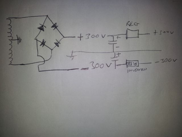
The other thought I had was to use 2 positive regulators but have the lower one referenced to 0V at the 'B+' output terminal. Using the simplified scheme I found on the net, in 'Option 2 I have tried to show how this might be configured.
If it works, the only downside is that I need a transformer with 2 separate windings and have to duplicate the bridge. I could then buy a pair of readily available pcbs or kits off the net.
- Attachments
-
TD-125/RB250/MC25FL & 'Snail' phono, NAS/SBT with CS4398 DAC, 41MP pre & MoFo Power, still messing with OBs.
-
Paul Barker
- Social Sevices have been notified
- Posts: 8988
- Joined: Mon May 21, 2007 9:42 pm
#4
That's what I meant. Floating means no ground reference externally. So to a floating reg your ground is it's + and your - out is it's "ground". Obviously it has to be carefully mounted and not touched.little eddy wrote: The other thought I had was to use 2 positive regulators but have the lower one referenced to 0V at the 'B+' output terminal.
"Two things are infinite, the universe and human stupidity, and I am not yet completely sure about the universe." – Albert Einstein
#5
If you intend to go from 300v to 150v with that supply, watch the dissipation on the mosfet.
Whenever an honest man discovers that he's mistaken, he will either cease to be mistaken or he will cease to be honest.
-
Paul Barker
- Social Sevices have been notified
- Posts: 8988
- Joined: Mon May 21, 2007 9:42 pm
#6
It's not outside the realms of possibility for a single valve to cope with the series pass duty. Would need careful consideration as it is a wide voltage range. As we have discussed the valve is the simplest and often cheapest, not to mention greatest space saving heatsink in these scenarios. though it needs a heater. Not to mention may sound better and much more tolerant of abuse than a mosfet. Mosfet is a fuse under stress, valve just glows a bit red, but lives to work again..Nick wrote:If you intend to go from 300v to 150v with that supply, watch the dissipation on the mosfet.
"Two things are infinite, the universe and human stupidity, and I am not yet completely sure about the universe." – Albert Einstein
-
Paul Barker
- Social Sevices have been notified
- Posts: 8988
- Joined: Mon May 21, 2007 9:42 pm
#7
So if you use 1/2 a 6080 and at 150v you allow 50v across it (any less would be poor regulation), then at 300v you are expecting it to handle 200v. With 13 watts max it can source up to 65mA. So it looks like a perfect candidate.
you would stretch the characteristics to use one valve because of the heater cathode problems as one half cathode stands at +300v and other at 0v. This is too close to call, The allowed potential is 300v. so if you ground the filament you are on the limit. You would want to elevate it to +150v for most reliable service.
you would stretch the characteristics to use one valve because of the heater cathode problems as one half cathode stands at +300v and other at 0v. This is too close to call, The allowed potential is 300v. so if you ground the filament you are on the limit. You would want to elevate it to +150v for most reliable service.
"Two things are infinite, the universe and human stupidity, and I am not yet completely sure about the universe." – Albert Einstein
-
little eddy
- Old Hand
- Posts: 693
- Joined: Sun Nov 09, 2008 2:06 pm
- Location: Manchester
#8
The board I linked to has a CRC filter before the regulator so I could limit the the total volt drop across the regulator. Would need to see the board as to what size heatsink could be used and then calculate max dissipation and hence range of adjustment.Nick wrote:If you intend to go from 300v to 150v with that supply, watch the dissipation on the mosfet.
TD-125/RB250/MC25FL & 'Snail' phono, NAS/SBT with CS4398 DAC, 41MP pre & MoFo Power, still messing with OBs.
-
little eddy
- Old Hand
- Posts: 693
- Joined: Sun Nov 09, 2008 2:06 pm
- Location: Manchester
#9
Paul - are you suggesting a valve regulated +/- 150V supply with IRF820 driver might sound better than a valve driver with SS +/- 300V rectification/regulation? Or might this be less risky to implement?Paul Barker wrote: Not to mention may sound better and much more tolerant of abuse than a mosfet.
Need to read up on Steve's valve regulation thread.
TD-125/RB250/MC25FL & 'Snail' phono, NAS/SBT with CS4398 DAC, 41MP pre & MoFo Power, still messing with OBs.
-
little eddy
- Old Hand
- Posts: 693
- Joined: Sun Nov 09, 2008 2:06 pm
- Location: Manchester
#10
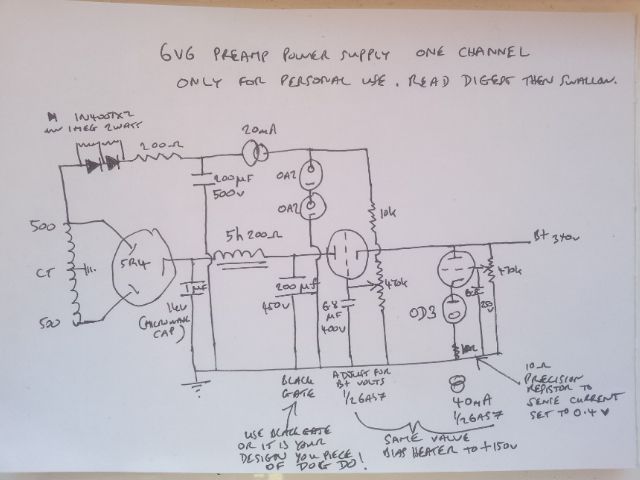
Well I've done some reading up on series-pass power supplies and have taken the 6AS7 series valve details from MJ and the lower 12AX7 lower half from a Rozenblit book.
As Paul suggested can bias the 6AS7 heater with the upper half reference voltage at half of the B+. EDIT - just noticed line that shouldn't be there between the grid of the upper valve to the heater bias potential divider.
The error valve heater bias is proving to be more difficult due to reduced cathode to heater specifications. Even the 12AX7 has a total limit of 300V so really pushing it at the +/-300V output (and the EF86 and 6SL7 have lower insulation levels).
Is there another error valve that can handle +/- 300V Vkh as the 6AS7, otherwise I may end up needing three valves?
I am assuming the upper error valve heater can be biassed with the 6AS7 so I could get away with just 2 heater supplies.
- Attachments
-
TD-125/RB250/MC25FL & 'Snail' phono, NAS/SBT with CS4398 DAC, 41MP pre & MoFo Power, still messing with OBs.
-
Paul Barker
- Social Sevices have been notified
- Posts: 8988
- Joined: Mon May 21, 2007 9:42 pm
#11
You don't have to use an error amplifier. Question? Are after a clever ultimate smoothing monster, or a good sounding power supply? It will take the rest of my life to finish playing with power supplies. Welcome to the journeys beginning.
"Two things are infinite, the universe and human stupidity, and I am not yet completely sure about the universe." – Albert Einstein
-
little eddy
- Old Hand
- Posts: 693
- Joined: Sun Nov 09, 2008 2:06 pm
- Location: Manchester
#12
Had only ever seen the 'error' type in any books I have. Did find this so guess circuit b could form the basis of an adjustable regulator: http://www.learn-about-electronics.com/ ... lator.htmlPaul Barker wrote:You don't have to use an error amplifier.
Needs some more head scratching though.
TD-125/RB250/MC25FL & 'Snail' phono, NAS/SBT with CS4398 DAC, 41MP pre & MoFo Power, still messing with OBs.
-
Paul Barker
- Social Sevices have been notified
- Posts: 8988
- Joined: Mon May 21, 2007 9:42 pm
#13
see next post.
Last edited by Paul Barker on Sun Jan 06, 2013 10:04 am, edited 1 time in total.
"Two things are infinite, the universe and human stupidity, and I am not yet completely sure about the universe." – Albert Einstein
-
Paul Barker
- Social Sevices have been notified
- Posts: 8988
- Joined: Mon May 21, 2007 9:42 pm
#14
Yes that's simplest. The regulation of b would be equivalent of choke input. Already a great improvement. But without the extra time taken to go round the error amplifier valve. Just more immediate. In an se amp the imediacy of power supply response plays music. Therefore the error amplifier is like adding feedback in the signal section. You wouldn't have dreamed of that and Therefore you wouldn't have dreamed of adding the error amplifier either, were you one of the pioneers of the rediscovery of simple se triode amps 15 to 20 years ago.
Today complexity of pathways has crept back. For the better? You decide. Try both? Try first choke input, try shunt regulation. Just try things, but with one eye on simplicity. Dont complain you haven't the transformer for choke input. You chose the transformer, your bad. No excuse.
Today complexity of pathways has crept back. For the better? You decide. Try both? Try first choke input, try shunt regulation. Just try things, but with one eye on simplicity. Dont complain you haven't the transformer for choke input. You chose the transformer, your bad. No excuse.
"Two things are infinite, the universe and human stupidity, and I am not yet completely sure about the universe." – Albert Einstein
-
Paul Barker
- Social Sevices have been notified
- Posts: 8988
- Joined: Mon May 21, 2007 9:42 pm
#15
This is my latest "ideal" power supply.
It has the cheap uncomplexed benefit of choke input.
It mirrors choke input with the simplest form of the series pass regulator but one that gives you a range of adjustment. The one you linked you would be limited by the value of the VR tubes available.
It finishes off with variable shunt regulation.
So there is complete flexibility but retains my roots. I learned about these things affecting sound in a single ended amplifier in small steps very early on, and what I learned I incorporate into my designs.
If I don't have the right transformer or choke for choke input, I wait until I do, or I compromise on the voltage I work with, or I don't build it.
Regarding banging on about choke input. I haven't altered my position since these days. The world has changed, fashions have changed but the best things for a single ended amp have not changed.
"Two things are infinite, the universe and human stupidity, and I am not yet completely sure about the universe." – Albert Einstein