I'm wiring up a common mode choke in a filament power supply - it's one of these http://www.rapidonline.com/Electronic-C ... d1b544afea
I'm a bit confused about how I should wire it up. Presumably it doesn't matter which winding comes first, but does there need to be some "polarity" of which end of each winding comes first? I think there must be otherwise the emi (emf?) of the two windings would compete?
Common Mode Chokes
-
IslandPink

- Amstrad Tower of Power
- Posts: 10041
- Joined: Tue May 29, 2007 7:01 pm
- Location: Denbigh, N.Wales
#2
The first pic of the inside of my phono :
http://www.audio-talk.co.uk/phpBB2/view ... 57&start=0
Should give you a clue .
The section of tag board on the lower edge of the picture, filament supply, has a CMC about 2/3rds of the way along from the Schottky diodes to the output . It straddles across from the + line ( upper edge ) to the ground line ( lower edge ) of the tag-board .
One winding goes in the + line, one goes in the ground or neg line . As far as connections goes, I just connected up the pins as they are then , input to the left pin, output from the right pin, in each line . I think (hope) that's the way the choke is set up ...
Maybe someone else has a better photo though .
"Once you find out ... the Circumstances ; then you can go out"
-
IslandPink
- Amstrad Tower of Power
- Posts: 10041
- Joined: Tue May 29, 2007 7:01 pm
- Location: Denbigh, N.Wales
#3
Not a lot more help, but here's another low-resolution pic ! :
http://www.audio-talk.co.uk/phpBB2/view ... c&start=45
http://www.audio-talk.co.uk/phpBB2/view ... c&start=45
"Once you find out ... the Circumstances ; then you can go out"
-
simon
- Thermionic Monk Status
- Posts: 5647
- Joined: Thu May 24, 2007 11:22 am
- Location: People's Republic of South Yorkshire
#4
Thanks Mark. I suppose it should be possible to measure which way round is the best connection, though as it's a CMC it probably needs more sophisticted kit than I have to replicate and measure RFI etc.IslandPink wrote:As far as connections goes, I just connected up the pins as they are then , input to the left pin, output from the right pin, in each line . I think (hope) that's the way the choke is set up ...
Maybe someone else has a better photo though .
-
Mike H

- Amstrad Tower of Power
- Posts: 20189
- Joined: Sat Oct 04, 2008 5:38 pm
- Location: The Fens
- Contact:
#5
I was trying to figure this out as well, I thought it was, as each end, with the pins closest together, is one winding, then one 'end' (2 pins) is in the live side and the other 'end' (2 pins) is in the ground side. But I wasn't sure if that made the two windings in phase if the 'inputs' & 'outputs' were each on the same longest side of the base. Or not...
"No matter how fast light travels it finds that the darkness has always got there first, and is waiting for it."
-
IslandPink
- Amstrad Tower of Power
- Posts: 10041
- Joined: Tue May 29, 2007 7:01 pm
- Location: Denbigh, N.Wales
#6
I'm trying to find a clear picture but it's a devil of a job. You'd think one of the manufacturers would think it was worth showing people exactly how to use them !
Yes, on each end, a pair of close pins is connected via a winding .
If you have the choke's long dimension across the board so one pair of close pins is on the + rail and one close pair is on the - rail ; then connect the input side on one side of the CMC and the output side on the other side . ie. attach input to one wide-spaced pair, and output to the other wide-spaced pair .
Does that describe it ?
"Once you find out ... the Circumstances ; then you can go out"
-
simon
- Thermionic Monk Status
- Posts: 5647
- Joined: Thu May 24, 2007 11:22 am
- Location: People's Republic of South Yorkshire
#7
Where I'm getting confused is whether the windings should be the same way or not, i.e. looking at the ferrite ring in side elevation (seeing the circle) if the input on the left hand side is in to the choke should the other side be wired out of or in to the choke? The coils are wired counter to each other so I wonder what will happen to the emf/emi but the more I think about it the more confused I get. Don't think I've explained any of that at all well.
-
pre65

- Amstrad Tower of Power
- Posts: 21400
- Joined: Wed Aug 22, 2007 11:13 pm
- Location: North Essex/Suffolk border.
#9
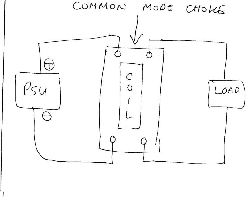
For what it's worth here's how I wired one up when I tried it.
The only thing necessary for the triumph of evil is for good men to do nothing.
Edmund Burke
G-Popz THE easy listening connoisseur. (Philip)
Edmund Burke
G-Popz THE easy listening connoisseur. (Philip)
-
Mike H
- Amstrad Tower of Power
- Posts: 20189
- Joined: Sat Oct 04, 2008 5:38 pm
- Location: The Fens
- Contact:
#11
I got it ~ Phil's drawing is the way, because -
1. that's the most obvious way to wire it, else why have to swap one of the pair of pins around?
2. studying the pictures, each winding is wound differently, one is wound clockwise, the other anti-clockwise.
Hence (below) 1 & 6 are in phase, 12 & 7 are in phase.
1. that's the most obvious way to wire it, else why have to swap one of the pair of pins around?
2. studying the pictures, each winding is wound differently, one is wound clockwise, the other anti-clockwise.
Hence (below) 1 & 6 are in phase, 12 & 7 are in phase.
- Attachments
-
- ccm.gif (2.34 KiB) Viewed 7221 times
"No matter how fast light travels it finds that the darkness has always got there first, and is waiting for it."
-
pre65
- Amstrad Tower of Power
- Posts: 21400
- Joined: Wed Aug 22, 2007 11:13 pm
- Location: North Essex/Suffolk border.
#12
What is the significance of the black spot ?
The only thing necessary for the triumph of evil is for good men to do nothing.
Edmund Burke
G-Popz THE easy listening connoisseur. (Philip)
Edmund Burke
G-Popz THE easy listening connoisseur. (Philip)

-
pre65
- Amstrad Tower of Power
- Posts: 21400
- Joined: Wed Aug 22, 2007 11:13 pm
- Location: North Essex/Suffolk border.
#14
I expected something like that, but from further south.Toppsy wrote:Depends if your name is Blind PewWhat is the significance of the black spot ?
The only thing necessary for the triumph of evil is for good men to do nothing.
Edmund Burke
G-Popz THE easy listening connoisseur. (Philip)
Edmund Burke
G-Popz THE easy listening connoisseur. (Philip)
-
Mike H
- Amstrad Tower of Power
- Posts: 20189
- Joined: Sat Oct 04, 2008 5:38 pm
- Location: The Fens
- Contact:
#15
"Deposed! And very pretty wrote" 
Dots at ends of windings tell you those ends are in phase.
Dots at ends of windings tell you those ends are in phase.
"No matter how fast light travels it finds that the darkness has always got there first, and is waiting for it."