It's been a while since I last used Duncan's PSU so can't recall when using a center taped TX do I enter both side of the winding or just the one
TX spec Old WD TOR300
195-0-195 @450mA
Secondary Resistance 28.Ohms
Primary Mains 40 Ohm s
Looking to Get HT of 280 Volts @240mA
last used Duncan’s PSU Help
-
colin.hepburn

- Shed dweller
- Posts: 2294
- Joined: Sat Jun 02, 2007 1:24 am
- Location: Scotland Aberdeenshire
#1 last used Duncan’s PSU Help
Colin
The Blues man

The Blues man
-
pre65

- Amstrad Tower of Power
- Posts: 21399
- Joined: Wed Aug 22, 2007 11:13 pm
- Location: North Essex/Suffolk border.
#2
If you use the centre tap then you enter one winding, but if you don't use centre tap (ie using a bridge rectifier) then enter both windings (ie 390v).
That's my understanding.
That's my understanding.
The only thing necessary for the triumph of evil is for good men to do nothing.
Edmund Burke
G-Popz THE easy listening connoisseur. (Philip)
Edmund Burke
G-Popz THE easy listening connoisseur. (Philip)
-
Mike H

- Amstrad Tower of Power
- Posts: 20189
- Joined: Sat Oct 04, 2008 5:38 pm
- Location: The Fens
- Contact:
#3
Apparently not ~ a case of choosing which style, full-wave or single, but the calc is on half of the full-wave, same as would be for whole single.
To reiterate, best way of setting it up is:
Choose transformer style.
Right mouse click on it to get 'Edit' pop-up ~ click link.
In the next window:
After first Volts box, click on '...' button.
In next window, type for 'nominal output', 195 (V)
Key tab.
In second text box '', type 0.45 (A)
Key tab.
In Regulation box, type 10 (%)
Key tab again to complete the remaining boxes, then 'OK'. That's it done.
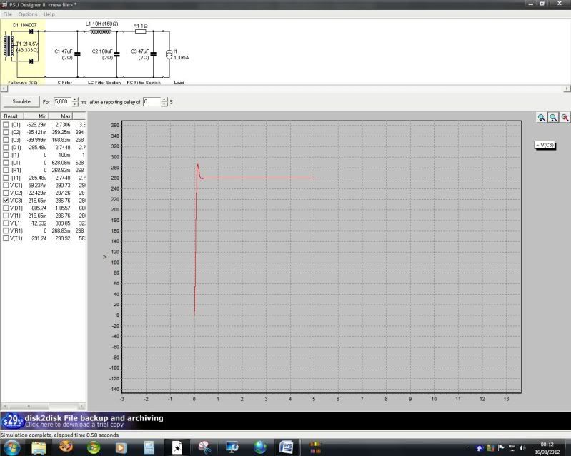
When I did it, came up with 214.5 RMS V and 43.333 Ohms
Same whether it's full-wave or single.
To reiterate, best way of setting it up is:
Choose transformer style.
Right mouse click on it to get 'Edit' pop-up ~ click link.
In the next window:
After first Volts box, click on '...' button.
In next window, type for 'nominal output', 195 (V)
Key tab.
In second text box '', type 0.45 (A)
Key tab.
In Regulation box, type 10 (%)
Key tab again to complete the remaining boxes, then 'OK'. That's it done.
When I did it, came up with 214.5 RMS V and 43.333 Ohms
Same whether it's full-wave or single.
"No matter how fast light travels it finds that the darkness has always got there first, and is waiting for it."
-
pre65
- Amstrad Tower of Power
- Posts: 21399
- Joined: Wed Aug 22, 2007 11:13 pm
- Location: North Essex/Suffolk border.
#4
I'm sure it's the whole winding for bridge rectifiers.(ie 390v)
The only thing necessary for the triumph of evil is for good men to do nothing.
Edmund Burke
G-Popz THE easy listening connoisseur. (Philip)
Edmund Burke
G-Popz THE easy listening connoisseur. (Philip)
-
Mike H
- Amstrad Tower of Power
- Posts: 20189
- Joined: Sat Oct 04, 2008 5:38 pm
- Location: The Fens
- Contact:
#5
I tried it to make sure, no it isn't. 
from help file:
"For full wave rectifiers, use the voltage for one side only. For example, if the transformer off load voltage is 350-0-350V (700V end to end), the correct value to enter is 350."
Help Contents > The Main Screen > Design area > transformers
from help file:
"For full wave rectifiers, use the voltage for one side only. For example, if the transformer off load voltage is 350-0-350V (700V end to end), the correct value to enter is 350."
Help Contents > The Main Screen > Design area > transformers
"No matter how fast light travels it finds that the darkness has always got there first, and is waiting for it."
-
Mike H
- Amstrad Tower of Power
- Posts: 20189
- Joined: Sat Oct 04, 2008 5:38 pm
- Location: The Fens
- Contact:
#6
Oh wait you mean if not using a CT then the whole lot becomes as per single winding, so is therefore each half x 2. However I thought Colin is using the CT for full-wave?
That TX will do 280VDC from 195VAC, + regulation overwind
That TX will do 280VDC from 195VAC, + regulation overwind
"No matter how fast light travels it finds that the darkness has always got there first, and is waiting for it."
-
colin.hepburn
- Shed dweller
- Posts: 2294
- Joined: Sat Jun 02, 2007 1:24 am
- Location: Scotland Aberdeenshire
#7
OK the possible plan is that I have ordered a matched quad set of the Russian 6P3S well they say matched as I want to to try a PSE version of this Schematic 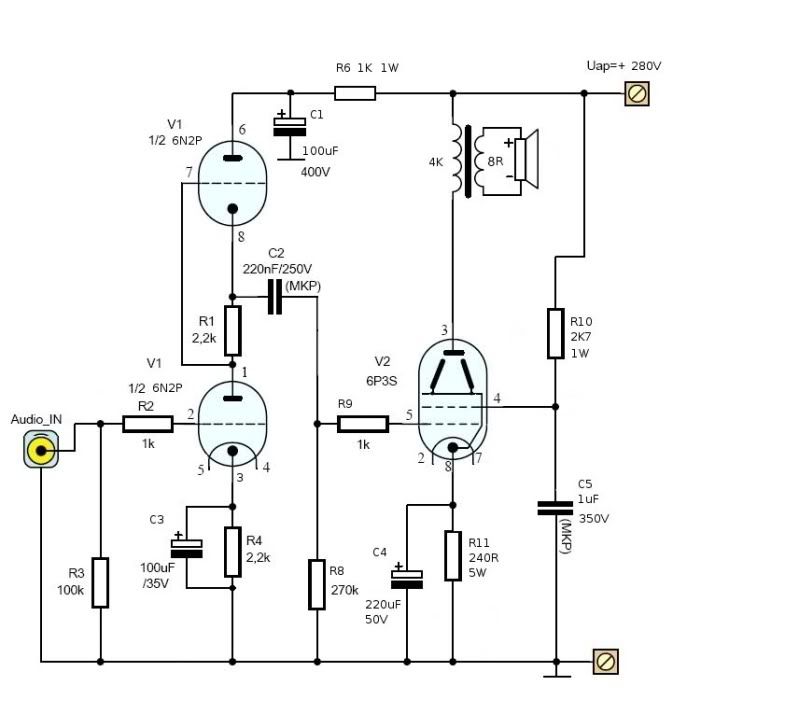
problem is this 6P3S valves spec is not to clear to me as it is said to be a 6P3S (6L6 5881 which all have different Anode voltages the 6p3s is said to be 250v anode but some have run it up to 400volts which just adds to the confusion I am still not sure what the cathode to ground is mA I am thinking around 60 mA this is all I can find on the spec that isn't in Russian http://www.hifitubes.nl/weblog/wp-conte ... 6p3s-e.pdf
problem is this 6P3S valves spec is not to clear to me as it is said to be a 6P3S (6L6 5881 which all have different Anode voltages the 6p3s is said to be 250v anode but some have run it up to 400volts which just adds to the confusion I am still not sure what the cathode to ground is mA I am thinking around 60 mA this is all I can find on the spec that isn't in Russian http://www.hifitubes.nl/weblog/wp-conte ... 6p3s-e.pdf
Colin
The Blues man
The Blues man
#8
might be a good front end for a 2A3....just saying!
There's nowhere you can be that isn't where you're meant to be
-
colin.hepburn
- Shed dweller
- Posts: 2294
- Joined: Sat Jun 02, 2007 1:24 am
- Location: Scotland Aberdeenshire
#9
Ok just using the default 100mA constant current and as mike suggested I get an HT of 260Volts
But if add in the correct winding resistance's for both primary 5.7R and secondary 14.00/28Rfor both sides I get more like 425 v HT
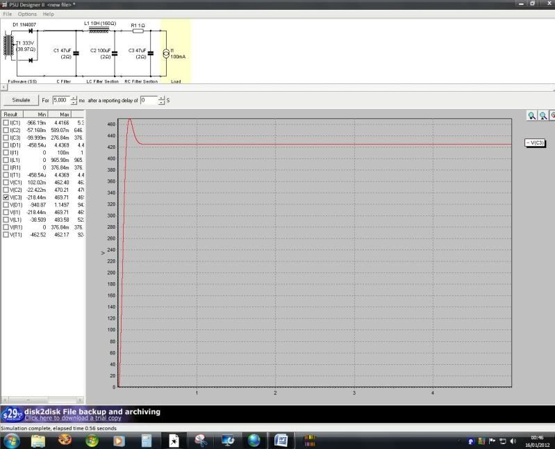
But if add in the correct winding resistance's for both primary 5.7R and secondary 14.00/28Rfor both sides I get more like 425 v HT
Colin
The Blues man
The Blues man
-
Mike H
- Amstrad Tower of Power
- Posts: 20189
- Joined: Sat Oct 04, 2008 5:38 pm
- Location: The Fens
- Contact:
#10
No, your transformer Voltage jumped back to the default 333V because you edited it (see top left of second pic) ~ every time you use the edit window it reverts to default, so you have to re-enter all the numbers again. Think that's right.
"No matter how fast light travels it finds that the darkness has always got there first, and is waiting for it."
-
Mike H
- Amstrad Tower of Power
- Posts: 20189
- Joined: Sat Oct 04, 2008 5:38 pm
- Location: The Fens
- Contact:
#11
PS: I prefer not to use a current source as the sole load, because it's unrealistic, most circuits supply current drain varies with Voltage hence I use a resistor. The value is whatever-you-think-the-Voltage-should-be divided by whatever-you-think-the-current-is.
In this case, 280 / 0.1
In this case, 280 / 0.1
"No matter how fast light travels it finds that the darkness has always got there first, and is waiting for it."
-
Mike H
- Amstrad Tower of Power
- Posts: 20189
- Joined: Sat Oct 04, 2008 5:38 pm
- Location: The Fens
- Contact:
#12
PPS: BTW you are losing nearly 20V in the choke alone, in case you hadn't noticed.
So 280V at the reservoir C1 would indeed come out more like 260 on C2 / C3, so it looks to me like the first pic #1 version is working correctly.
EDIT: or as I anticipated even.
Reason for edit: typos (number wrong)
So 280V at the reservoir C1 would indeed come out more like 260 on C2 / C3, so it looks to me like the first pic #1 version is working correctly.
EDIT: or as I anticipated even.
Reason for edit: typos (number wrong)
Last edited by Mike H on Mon Jan 16, 2012 4:25 pm, edited 1 time in total.
"No matter how fast light travels it finds that the darkness has always got there first, and is waiting for it."
-
colin.hepburn
- Shed dweller
- Posts: 2294
- Joined: Sat Jun 02, 2007 1:24 am
- Location: Scotland Aberdeenshire
#13
Ok right tried again and I get 256v HT
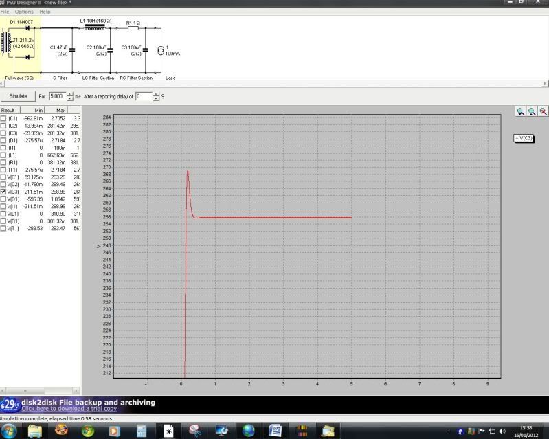
But the following Schematic is the psu for the WD kit 88 pp amp which is used the same TOR 300 TX and ht is much higher but don't know what current the kit 88 is pulling thou
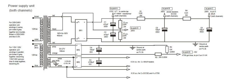
But the following Schematic is the psu for the WD kit 88 pp amp which is used the same TOR 300 TX and ht is much higher but don't know what current the kit 88 is pulling thou
Colin
The Blues man
The Blues man
-
colin.hepburn
- Shed dweller
- Posts: 2294
- Joined: Sat Jun 02, 2007 1:24 am
- Location: Scotland Aberdeenshire