Hmmm...
I read somewhere that as the HT drops from increased current flow, the gain reduces, resulting in some compression of the signal. Not sure how much compression it'll be in the grand scheme of things though.
A p/p might be next on the list, Mike: I have two of these 6550s, but the extra iron could start getting expensive methinks.
A foray into the world of glowy stuff.
-
Mike H

- Amstrad Tower of Power
- Posts: 20189
- Joined: Sat Oct 04, 2008 5:38 pm
- Location: The Fens
- Contact:
#152
Yes that's the idea, just not sure how well it would work with SE, but only one way to find out. 
"No matter how fast light travels it finds that the darkness has always got there first, and is waiting for it."
#153
Dad's just pointed out that the mains TX I've found doesn't have a centre-tapped HT. That's probably why its so cheap.
I could go for half-wave rectification (and parallel the rectifier diodes for reduced impedance there) - is that likely to suffice?
I could go for half-wave rectification (and parallel the rectifier diodes for reduced impedance there) - is that likely to suffice?
-
Cressy Snr

- Amstrad Tower of Power
- Posts: 10582
- Joined: Wed May 30, 2007 12:25 am
- Location: South Yorks.
#154
If there is no centre tap, simply use a bridge rectifier, either solid state or a hybrid bridge with two ss diodes and a valve rectifier. If you look at the schematic I posted in my thread about my 6P25 monoblocks you will see how a hybrid bridge is done.
Problem solved.
Problem solved.
Sgt. Baker started talkin’ with a Bullhorn in his hand.
#157
So far, I haven't had any luck in getting myself a suitable transformer on eBay - they always seem to go for ~£5 more than I bid.
So I've had this idea.
I have a pair of mains transformers, each with split secondary windings (the secondary windings are 26-0-26, with a 4A fuse on each).
So what if I connect up the variac to the secondaries (wired in series) to get the right voltage at the primary taps (which would also be wired in series)?
There would be isolation from the mains, and, so far as I can tell, none of the transformer ratings would be passed.
Proposed diagram attached.
Couple of diodes needed to complete the bridge rectifier, but that shouldn't be a problem.
Anyone got any thoughts on this?
Cheers
Chris
- Attachments
-
-
Paul Barker

- Social Sevices have been notified
- Posts: 8995
- Joined: Mon May 21, 2007 9:42 pm
#158
It relies on the wire used on the variac having the current rating of the 26v 4A wire used on the trasnformer, which is unlikely, but possible. I would say your variac needs to be a large 3kw 13A one.
Then do not exceed the maximum of 52v which would be the correct voltage of the transformers secondaries (now primaries) in series. So your secondary, so your new secondary is 240 - 0 - 240 (known as 480v centre tapped) be careful to get phasing right. Or you can connect it as 480v for bridge rectifying or anything below 240 - 0 - 240 (or below 480v) but nothing above.
Then do not exceed the maximum of 52v which would be the correct voltage of the transformers secondaries (now primaries) in series. So your secondary, so your new secondary is 240 - 0 - 240 (known as 480v centre tapped) be careful to get phasing right. Or you can connect it as 480v for bridge rectifying or anything below 240 - 0 - 240 (or below 480v) but nothing above.
"Two things are infinite, the universe and human stupidity, and I am not yet completely sure about the universe." – Albert Einstein
-
Mike H
- Amstrad Tower of Power
- Posts: 20189
- Joined: Sat Oct 04, 2008 5:38 pm
- Location: The Fens
- Contact:
#159
Took me a few minutes to get my head around this 
Ah OK
Or, another idea that I've seen in old books (but not tried it TBH), if you've two of these transformers, run one off the mains as normal, run the 26-0-26 sec into the second one's 26-0-26 sec, then you get 240VAC off the second one's primary. You essentially get mains Voltage, but isolated from the actual mains.
"No matter how fast light travels it finds that the darkness has always got there first, and is waiting for it."
-
pre65

- Amstrad Tower of Power
- Posts: 21400
- Joined: Wed Aug 22, 2007 11:13 pm
- Location: North Essex/Suffolk border.
#160
That would also be my suggestion.Mike H wrote:
Or, another idea that I've seen in old books (but not tried it TBH), if you've two of these transformers, run one off the mains as normal, run the 26-0-26 sec into the second one's 26-0-26 sec, then you get 240VAC off the second one's primary. You essentially get mains Voltage, but isolated from the actual mains.
The only thing necessary for the triumph of evil is for good men to do nothing.
Edmund Burke
G-Popz THE easy listening connoisseur. (Philip)
Edmund Burke
G-Popz THE easy listening connoisseur. (Philip)
#162
That'll work, Mike, but I need more than mains voltage to get the 400V DC HT after rectifier sag.
The variac here is about 3kW rated, Paul. It's a big 'un.
Both transformers would have their secondaries in series, so I'm fairly sure that comes to 104v maximum from the variac (above this is beyond the ratings of the transformers).
That'd give 480v AC output, which is far more than needed.
I would guess I need around 300v from the transformer, which would give 420v DC, minus a bit for the series resistance of the valve rectifier.
It sounds like the idea will work, so I'll apply heater voltages, then slowly bring the HT up.
Chris

#164
Just got home again, so I'm back on this.
300v RMS = 424.26...v peak.
Sounds about right - once rectified it'll sit near 400v. The variac means I can dial it in fairly precisely to whatever I like. The PSU caps are 400v rated, so I don't plan on going any higher.
I'm not sure if there are any suitable diodes in stock, so it looks like a trip to Maplin is in order - I don't think Mother will appreciate the smell of burnt-out diodes wafting through the house.
#165
Rigged up the transformers as shown in the circuit diagram further up.
Turned it up to 450v RMS on the output, and decided that's probably enough.
Haven't tried taking any current yet, but I'd estimate ~400mA before the fuses on the 26-0-26 windings go. Should be plenty enough - IIRC, the 6550 in the amplifier is biased for 80mA, with the other valves drawing negligible current in comparison.
I'll be in town tomorrow, so will pick up some high voltage diodes at Maplin. 39p each
For my own reference,
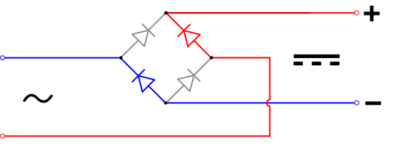
I assume the valve rectifier is to take the place of the red and upper grey diodes, with silicon diodes being the bottom two - would appreciate if someone could confirm this, as Steve's thread with a clear diagram of a hybrid rectifier has gone AWOL.
Cheers
Chris
Turned it up to 450v RMS on the output, and decided that's probably enough.
Haven't tried taking any current yet, but I'd estimate ~400mA before the fuses on the 26-0-26 windings go. Should be plenty enough - IIRC, the 6550 in the amplifier is biased for 80mA, with the other valves drawing negligible current in comparison.
I'll be in town tomorrow, so will pick up some high voltage diodes at Maplin. 39p each
For my own reference,
I assume the valve rectifier is to take the place of the red and upper grey diodes, with silicon diodes being the bottom two - would appreciate if someone could confirm this, as Steve's thread with a clear diagram of a hybrid rectifier has gone AWOL.
Cheers
Chris