Paul.....So what you are saying is that this totem pole regulator setup is going to introduce nasties into the sound of the amplifiers, because the PSU is part of the signal path.
So taking it to its logical conclusion I'm in danger of turning a great amp; one that gave a sound through
James' speakers, at Owston that was in the same league as the legendary Jono 45 amp
moment at Eggborough, into nothing more than an also ran?
If that is the case, maybe I'm just better leaving well-enough alone.
SRPP Series Shunt Reg Anyone?
-
Cressy Snr

- Amstrad Tower of Power
- Posts: 10576
- Joined: Wed May 30, 2007 12:25 am
- Location: South Yorks.
-
Paul Barker

- Social Sevices have been notified
- Posts: 8969
- Joined: Mon May 21, 2007 9:42 pm
#32
No.SteveTheShadow wrote:Paul.....So what you are saying is that this totem pole regulator setup is going to introduce nasties into the sound of the amplifiers, because the PSU is part of the signal path.
All I am saying is that an SRPP is an entirely different beast to what you have and not many of those are a success.
Regarding the power supply being part of the signal path is exactly why I would have a shunt valve proximal to the signal valves, and minimise any other means of power supply smoothing in favour of it. Or eliminate them.
then you will have what you already have plus improvement.
-
Cressy Snr
- Amstrad Tower of Power
- Posts: 10576
- Joined: Wed May 30, 2007 12:25 am
- Location: South Yorks.
#33
OK so not as bad as I thought. 
As I said earlier I'll try it with the Zeners first, then if it works and sounds promising
I can set it up with VR tubes.
I suppose the gist of the matter is that you can't just go around calling any old totem pole circuit an SRPP then?
As I said earlier I'll try it with the Zeners first, then if it works and sounds promising
I can set it up with VR tubes.
I suppose the gist of the matter is that you can't just go around calling any old totem pole circuit an SRPP then?
-
Paul Barker
- Social Sevices have been notified
- Posts: 8969
- Joined: Mon May 21, 2007 9:42 pm
#34
Well on a certain level people call that layout SRPP. But as that article shows there are depths to be explored.
The main thing about your circuit is the entirely different currents of each section. The writer of that article would have a heart attack.
The main thing about your circuit is the entirely different currents of each section. The writer of that article would have a heart attack.
-
Paul Barker
- Social Sevices have been notified
- Posts: 8969
- Joined: Mon May 21, 2007 9:42 pm
#35
Forgeting terminology ther greatest advancement in the last few days is the evolution of a way to shunt regulate using a VR tube and a cheap yet appropriate valve which must be negatively biased without the need for a negative supply.
This could be applied in so many places and bring the joys of shunt regulation to the masses.
I had been using positive bias valves following Steve Benches pages for years without applying my mind to another solution. Here it is.
However for low voltages the 830b does do the Steve Bench well and for high voltages the 572b does also, so I don't see the need to change what I have.
If I needed to hash up another though I would go with what you have there.
Although it is credible to evaluate using a zenner ref. the audio ac signal passes right through it, and therefore the design in audiophile terms has to contain the VR tube as the reference. Zenners on cathodes sound nasty.
-
Cressy Snr
- Amstrad Tower of Power
- Posts: 10576
- Joined: Wed May 30, 2007 12:25 am
- Location: South Yorks.
#36
Don't fret Paul I'm not about to fsck things up with ZenersPaul Barker wrote: Although it is credible to evaluate using a zenner ref. the audio ac signal passes right through it, and therefore the design in audiophile terms has to contain the VR tube as the reference. Zenners on cathodes sound nasty.
It's just an exercise to see if the thing works as predicted.
Just thinking aloud:
lower power series/shunt regs could be done with dual triodes such as 7044s 6463s, E182CCs 6N6Ps and 12B4As. Computer or telly valves that nobody uses could be pressed into service in this config. What the results would be I don't know but it would be fun trying.
-
Paul Barker
- Social Sevices have been notified
- Posts: 8969
- Joined: Mon May 21, 2007 9:42 pm
#37
YEs..
I am a little worried that there will ensue a run on 75C1's.
Fortunately I have mine.
But observant ones will see how many I have to use. After the two sent to you there are no spares. I would have to migrate them from amp to amp to build anything else with them.
At the end of the day a good sounding VR capable of all the current which satisfactorily controls voltage (which most VR's don't do) is the key to success.
You can even use them as a direct coupling mechanism in place of a coupling cap. You just have to send a current through them to strike them. they then hold the two stages at two different potentials yet pass the AC signal, and quite likely do so better than a capacitor.
Last edited by Paul Barker on Fri Dec 30, 2011 7:20 pm, edited 1 time in total.
-
Cressy Snr
- Amstrad Tower of Power
- Posts: 10576
- Joined: Wed May 30, 2007 12:25 am
- Location: South Yorks.
#38
There's always the QS75/60 loktal one.Paul Barker wrote:YEs..
I am a little worried that there will ensue a run on 75C1's.
Fortunately I have mine.
-
Paul Barker
- Social Sevices have been notified
- Posts: 8969
- Joined: Mon May 21, 2007 9:42 pm
#39
well it may be good, everything has to be tested in the field. the 75c1 has been tested and found satisfactory.
I was shocked at the massive variation between my s130's. What a shame.
I was shocked at the massive variation between my s130's. What a shame.
-
Paul Barker
- Social Sevices have been notified
- Posts: 8969
- Joined: Mon May 21, 2007 9:42 pm
#40
Might hook it up myself.
-
Paul Barker
- Social Sevices have been notified
- Posts: 8969
- Joined: Mon May 21, 2007 9:42 pm
#41
huston we have another problem.
You need more than 75v on the cathode.
Here are the rough calcs for what I need.
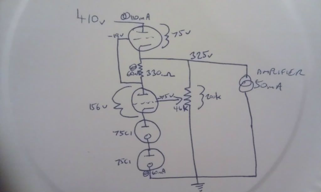
Second problem. the 330 ohm resistor is in the signal path of the return ac audio loop. you could bypass it with a cap if you weren't a cap hater.
This fact alone makes me want to not run the circuit as a combination valve, rather to run the first section with another error amplifier place a choke after that stage then run the second section as a pure shunt valve with no series resistor.
You need more than 75v on the cathode.
Here are the rough calcs for what I need.
Second problem. the 330 ohm resistor is in the signal path of the return ac audio loop. you could bypass it with a cap if you weren't a cap hater.
This fact alone makes me want to not run the circuit as a combination valve, rather to run the first section with another error amplifier place a choke after that stage then run the second section as a pure shunt valve with no series resistor.
-
Cressy Snr
- Amstrad Tower of Power
- Posts: 10576
- Joined: Wed May 30, 2007 12:25 am
- Location: South Yorks.
#42
Hmm yeah you can't get the right bias with only 75V can you
I was just going to post the very same after poring over curves myself.
That's why I had the cathode of the bottom valve elevated that high.
I remember now.
I get nervous when questioned by people who know more than me these days.
Never used to bother me when I was a young rebel but now I'm like the absent minded professor, except I'm not a professor:D
That's why I do supply teaching these days. Nobody asks me anything.
BUt calming down, I might be able to juggle something with a 6336.
#43
Previously I designed the attached psu for Dave Dove's RIAA amp using a TV dual triode  It would have been better with a VR ref in their somewhere on the shunt but not sure that a 75V VR tube would work at these B+ volts... and , following this discussion the BG should come out!
This is a fantastic discussion to follow as you both give your thoughts and reasoning. And Paul, your accounts of your experience is wonderful! Many thanks to you both for doing this on the forum.
James
This is a fantastic discussion to follow as you both give your thoughts and reasoning. And Paul, your accounts of your experience is wonderful! Many thanks to you both for doing this on the forum.
James
- Attachments
-
- DD_RIAA_HT_Power_supply.GIF (9.4 KiB) Viewed 5536 times
-
Cressy Snr
- Amstrad Tower of Power
- Posts: 10576
- Joined: Wed May 30, 2007 12:25 am
- Location: South Yorks.
#44
Hi James
I knew somebody, somewhere would have done something similar.
Well you could try it out Paul despite the resistor, are you really going to hear that single resistor in your psu
I knew somebody, somewhere would have done something similar.
Well you could try it out Paul despite the resistor, are you really going to hear that single resistor in your psu
-
Paul Barker
- Social Sevices have been notified
- Posts: 8969
- Joined: Mon May 21, 2007 9:42 pm
#45
The antedote:
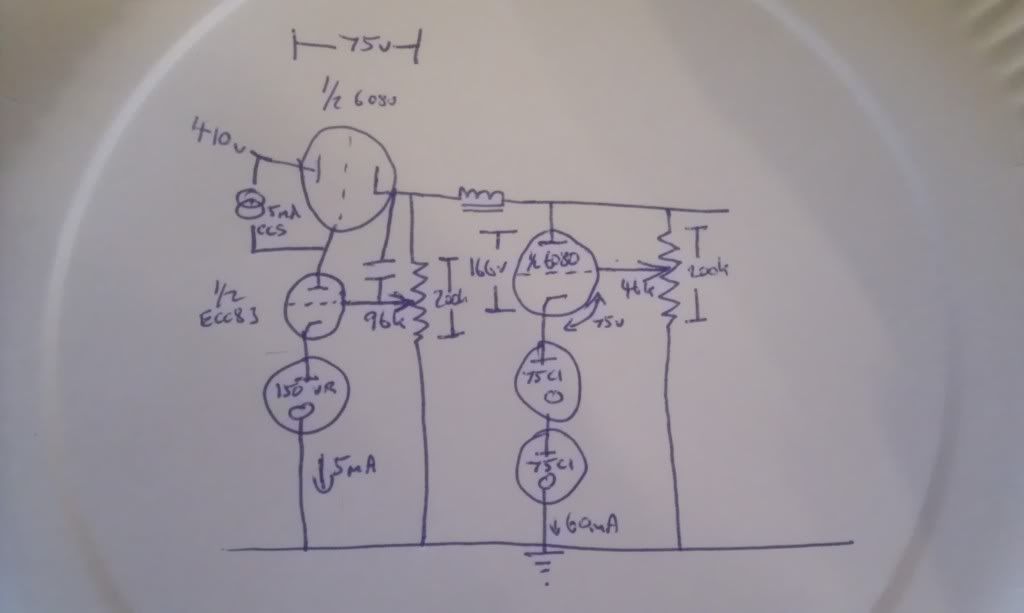
The antedote has three superior features.
1/ reduction of series resistance of AC signal loop.
2/ vastly improved error amplifier
3/ isolation of horrible series pass regulation from AC signal loop by superior shunt regulation after a necessary isolating choke which had better be wound for HF by sectioning wave winding or jumble winding..
There is a minimum of 5mA required for the 150v reg. It may prove necessary to send it some current via a bypass resistor from source or it may not strike.
The 75c1's should strike but I would also stand ready to flash them from B+ to start them if necessary. If I build it I will tell you. We are already using their maximum current capacity so can't send them a bleed.
My present shunt valve for this amp is already built and sorted the 830b with three 75c1's on the grid works out just fine although it is pulling a healthy 100mA so it is a different power supply but the transformer is rated at 500mA and if I use two halves of 6080 series pass element they can cope with the total 150mA.
Last edited by Paul Barker on Sat Dec 31, 2011 8:32 am, edited 1 time in total.