Power op amp driving valve in A2
-
Mike H

- Amstrad Tower of Power
- Posts: 20189
- Joined: Sat Oct 04, 2008 5:38 pm
- Location: The Fens
- Contact:
#17
Yes I'd managed to forget it as well!Lee S wrote:Aaaargh !!! Paul !!! I had just about forgotten about that bloke until you mentioned it again.... Horror !!!
Too much information!Paul Barker wrote:However a friend of mine aparently wins the hairiest backside contest, I heard tonight when he was passed out naked on the bathroom floor his wife sent for her friend to lift him into bed.
"No matter how fast light travels it finds that the darkness has always got there first, and is waiting for it."
-
Mike H
- Amstrad Tower of Power
- Posts: 20189
- Joined: Sat Oct 04, 2008 5:38 pm
- Location: The Fens
- Contact:
#18
Off-topic suggestion for Nick ~ as regards use of an op-amp to regulate a supply rail (low impedance negative as well as positive) how about one of these power amp chips like TDA2050? Is wired up same as an op-amp. 
"No matter how fast light travels it finds that the darkness has always got there first, and is waiting for it."
-
pre65

- Amstrad Tower of Power
- Posts: 21400
- Joined: Wed Aug 22, 2007 11:13 pm
- Location: North Essex/Suffolk border.
#19
Class D old chap.Mike H wrote:A T-amp is class C output? I wouldn't, could have HF flying around everywhere
Would do as a first step though, to test the concept without investing to much spondoolicks ?
The only thing necessary for the triumph of evil is for good men to do nothing.
Edmund Burke
G-Popz THE easy listening connoisseur. (Philip)
Edmund Burke
G-Popz THE easy listening connoisseur. (Philip)
-
Mike H
- Amstrad Tower of Power
- Posts: 20189
- Joined: Sat Oct 04, 2008 5:38 pm
- Location: The Fens
- Contact:
#20
Oh right I keep getting it wrong, class D 
I know what I meant.
You can try it but I'm not sure meself.
I know what I meant.
You can try it but I'm not sure meself.
"No matter how fast light travels it finds that the darkness has always got there first, and is waiting for it."
-
pre65
- Amstrad Tower of Power
- Posts: 21400
- Joined: Wed Aug 22, 2007 11:13 pm
- Location: North Essex/Suffolk border.
#21
I might just, as an experimentalisation to keep me amused on cold winters days.Mike H wrote:Oh right I keep getting it wrong, class D
I know what I meant.
You can try it but I'm not sure meself.
The old T-amp has got to be good for something.
Next up I need a design for a 250v (220-250v variable ideally) regulated PSU to power the 1626 valves. Each valve is 30ma so 60 + ma needed. The transformer will be the one from my original 300b amp so there are a few volts to spare.
The only thing necessary for the triumph of evil is for good men to do nothing.
Edmund Burke
G-Popz THE easy listening connoisseur. (Philip)
Edmund Burke
G-Popz THE easy listening connoisseur. (Philip)
-
pre65
- Amstrad Tower of Power
- Posts: 21400
- Joined: Wed Aug 22, 2007 11:13 pm
- Location: North Essex/Suffolk border.
#22
I've decided to go with a simple PSU to start with.
I have a Danbury 260v mains transformer and a couple of 10H chokes.
In fact I could use 3 chokes and split the supply after the first choke, that would give each channel it's own choke.
I have a Danbury 260v mains transformer and a couple of 10H chokes.
In fact I could use 3 chokes and split the supply after the first choke, that would give each channel it's own choke.
The only thing necessary for the triumph of evil is for good men to do nothing.
Edmund Burke
G-Popz THE easy listening connoisseur. (Philip)
Edmund Burke
G-Popz THE easy listening connoisseur. (Philip)
-
pre65
- Amstrad Tower of Power
- Posts: 21400
- Joined: Wed Aug 22, 2007 11:13 pm
- Location: North Essex/Suffolk border.
#23
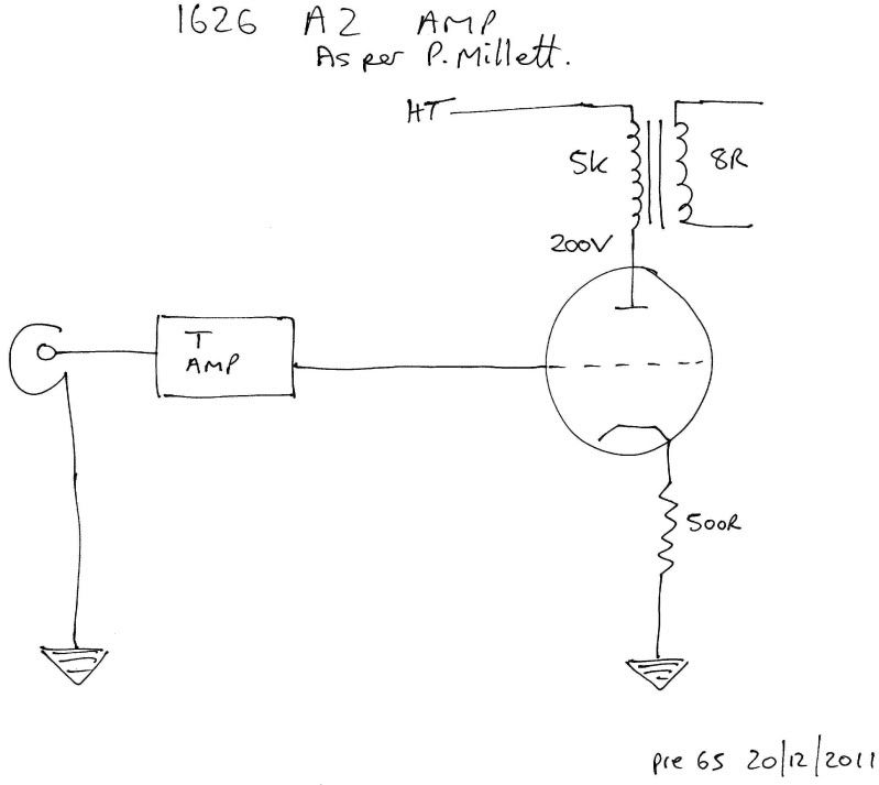
Thinking about this amp, and having discussed it with a friend, I'm confused as how A2 operation will affect the t-amp driving the grid.
I've drawn the circuit as I understand it from P.Millett's article. Is it as simple as having a cap between t-amp and 1626 grid to protect the t-amp from grid current in A2 ?
Or is it more complicated perhaps ?
http://www.pmillett.com/pwrop.htm
PS there are 2 caps shown in the article picture, one seems to be a bypass cap for the cathode resistor.
The only thing necessary for the triumph of evil is for good men to do nothing.
Edmund Burke
G-Popz THE easy listening connoisseur. (Philip)
Edmund Burke
G-Popz THE easy listening connoisseur. (Philip)
-
Mike H
- Amstrad Tower of Power
- Posts: 20189
- Joined: Sat Oct 04, 2008 5:38 pm
- Location: The Fens
- Contact:
#24
Can't put a capacitor in, would just be charged up, and the grid would end up zero or negative, we've been down this road before haven't we?
Output must be DC coupled to grid, and the current will be all in one direction, that's one reason why I wasn't sure a if a T-amp would be suitable.
Output must be DC coupled to grid, and the current will be all in one direction, that's one reason why I wasn't sure a if a T-amp would be suitable.
"No matter how fast light travels it finds that the darkness has always got there first, and is waiting for it."
-
pre65
- Amstrad Tower of Power
- Posts: 21400
- Joined: Wed Aug 22, 2007 11:13 pm
- Location: North Essex/Suffolk border.
#25
OK, so would your suggestion of the Maplin amp be any different ?Mike H wrote:
Output must be DC coupled to grid, and the current will be all in one direction, that's one reason why I wasn't sure a if a T-amp would be suitable.
The only thing necessary for the triumph of evil is for good men to do nothing.
Edmund Burke
G-Popz THE easy listening connoisseur. (Philip)
Edmund Burke
G-Popz THE easy listening connoisseur. (Philip)
-
Mike H
- Amstrad Tower of Power
- Posts: 20189
- Joined: Sat Oct 04, 2008 5:38 pm
- Location: The Fens
- Contact:
#26
I would think so because it's linear not class D. Have no personal experience of class D but am given to understand the output is like a high freq. square wave with variable mark-space ratio, followed by substantial filtering to then get rid of it, leaving just the DC shift resulting from the difference in mark-space ratio. Don't think you can give it complicated one-sided loads, like a diode, which is what a valve grid is like.
"No matter how fast light travels it finds that the darkness has always got there first, and is waiting for it."
-
Mike H
- Amstrad Tower of Power
- Posts: 20189
- Joined: Sat Oct 04, 2008 5:38 pm
- Location: The Fens
- Contact:
#28
I rather thought so too.
Somone else more up on the theory of how they work might be able to confirm, or not....
Somone else more up on the theory of how they work might be able to confirm, or not....
"No matter how fast light travels it finds that the darkness has always got there first, and is waiting for it."
#29
I did this a while back, with Nick's help I managed to stabilize it, so it didn't continually blow up op amps, was proving a bit expensive up until then.Mike H wrote:Off-topic suggestion for Nick ~ as regards use of an op-amp to regulate a supply rail (low impedance negative as well as positive)
Andrew
Analogue, the lost world that lies between 0 and 1.
#30
If I remember correctly, we got through a lot of desoldering braid that dayAndrew wrote:I did this a while back, with Nick's help I managed to stabilize it, so it didn't continually blow up op amps, was proving a bit expensive up until then.Mike H wrote:Off-topic suggestion for Nick ~ as regards use of an op-amp to regulate a supply rail (low impedance negative as well as positive)
Andrew
Whenever an honest man discovers that he's mistaken, he will either cease to be mistaken or he will cease to be honest.