Just because I want to learn a bit more I've been looking through Valve data sheets for the above valves trying to work out little differences between them all and more to the point what makes certain valves sound that bit extra 'magic'.
I know AndrewI has said in the past that he likes 6DN7 marginally over 6EM7.
Looking at the 2 side by side shows that Triode 1 in each valve is pretty much the same but the power Triodes have very different interelectrode capacitances EG 6EM7 Grid to plate 10pF whereas 6DN7 is only 5.5pF. 6DN7's Anode voltage can be run much higher at 550V too (6EM7=330V) but plate dissipation is the same at 10W.
Amplification factor on 6DN7(22.5) is lower in Triode 1 than 6EM7(64) but it's swapped in Triode 2 6DN7 (15.4) and 6EM7 (5.4).
Transconductance is hugely different 6DN7 2500 u to 7200u of 6EM7.
Plate resistance is very different too, 6DN7 9K and 2K and 6EM7 40K and 750R.
Which brings us to 6GL7, is this a hidden gem? It's looks right inbetween 6DN7 and 6EM7.
Just wondering and trying to learn stuff.
As an exercise I was wondering if seeing as it's a 'compactron' if I could try and design a very simple amp with it but actually try and work out the component values myself (design..eek), natch I'd need help or gentle hints.
Good idea or too ambitious?
Be honest.
Ta
DTB
6EM7-6DN7-6GL7 Familly
-
Dave the bass

- Amstrad Tower of Power
- Posts: 12276
- Joined: Tue May 22, 2007 4:36 pm
- Location: NW Kent, Darn Sarf innit.
#1 6EM7-6DN7-6GL7 Familly
"The fat bourgeois and his doppelganger"
-
andrew Ivimey

- Social Sevices have been notified
- Posts: 8318
- Joined: Mon Jun 11, 2007 8:33 am
- Location: Bedford
#2
Its the only way Dave, well done!
-
Cressy Snr

- Amstrad Tower of Power
- Posts: 10582
- Joined: Wed May 30, 2007 12:25 am
- Location: South Yorks.
#3
It's the way I did it Dave.
I made a few mistakes along the way but never made a bad sounding
amp. You learn so much more designing your own gear
than you do by building published circuits.
Steve
I made a few mistakes along the way but never made a bad sounding
amp. You learn so much more designing your own gear
than you do by building published circuits.
Steve
-
Dave the bass
- Amstrad Tower of Power
- Posts: 12276
- Joined: Tue May 22, 2007 4:36 pm
- Location: NW Kent, Darn Sarf innit.
#4
Cor, ta for the support Gents, thanks.
My challenge to myself is to see if I can make some kind of SE amp out of 6GL7 only because I've not heard of anyone else doing it before, probably 'cos it's a minger possibly (?)... I dunno, but it looks 'sorta-like' 6DN7/6EM7 and from the spec it's a bit inbetween like I said above so that's my first decision.
Secondly it's a double triode so that should make things easier for me as I've got a sort of reference in what I've built before.
First step I guess is find some more data so after my dinner and shower I'll scour the web for loadlines 'cos thats where you start I guess.
If the loadlines look like the tube map I'll assume I've made a bad decision and give up!
Back soon,
DTB
"The fat bourgeois and his doppelganger"
#5
There is also the novar 6gf7 which has the first triode from a 6dn7 and the second from a 6em7. I have used that to drive a 300b with good results.
Dave, you could always plot your own load lines, all you need is an adjustable B+ source, a adjustable negative bias supply, maybe a few 9v batteries and a pot. And current meter, or voltmeter and 10 ohm resistor.
Dave, you could always plot your own load lines, all you need is an adjustable B+ source, a adjustable negative bias supply, maybe a few 9v batteries and a pot. And current meter, or voltmeter and 10 ohm resistor.
Whenever an honest man discovers that he's mistaken, he will either cease to be mistaken or he will cease to be honest.
-
Dave the bass
- Amstrad Tower of Power
- Posts: 12276
- Joined: Tue May 22, 2007 4:36 pm
- Location: NW Kent, Darn Sarf innit.
#6
OK Nick, I'll bite.
<Rubs chin and looks up at the ceiling> "Hmmm...diy loadlines y'say?"
Really? I can muster up a 0-350VDC (250mA) PSU and another 0-30V DC (at 3Amp) for bias supply and I have an old Maplin XP27 TX I could use for the heater supply.
I have pot..I mean I have a potentiometer and resistors. I'll get a few 9V batteries too. (This sounds like Blue Peter, will I need sticky-back plastic and a grown up with a sharp knife?).
I'm all ears Nick, fire away. Well tomorrow lunchtime I should be able to play Mr Loadline plotter, I suppose I'd best buy a pair of 6GL7's first though yes?
Could I practise on a spare 6EM7 first? I think the pin-outs are the same.
DTB
"The fat bourgeois and his doppelganger"
#7
Yep, its simple enough.
Connect the valve heater up, connect the B+ supply across the valve + to anode, 0v to cathode. If you need a sense resistor to measure current it between the anode and +ve. Then connect the low voltage supply (if its adjustable you don't need a pot) in reverse with 0v on the grid, and +ve to the cathode (this assumes at least of the power supplies are floating).
Make a guess at the max current through the valve (to avoid working it to hard, you may get that from the spec). Say 2ma for the small triode, and 50ma for the bigger one. Not such a limit at low anode voltages.
Start with the grid at 0v, then increase the anode voltage (say) 50v at a time, and note the current. Repeat this untill max anode voltage.
Then increase the grid voltage, by (say) 1v for the small triode, and 10v for the large one, so its now negative with respect to the cathode. Then repeat the anode voltage sweep from 0v to max, noting he current.
Do this up to the max grid voltage, plot the points and joine the points for each setting of grid voltage, and there you are, DIY anode curves.
Hopefully that makes sense.
Actually, if you do create those curves Dave, maybe you can write what you then go on to do with them, this might form a good way of creating the "how to use loadlines" I said I was going to write.
You could take this post as the first part, "how to create the anode curves".
Once you have done that, you could create the other set of common curves. The grid curves. Keep the anode voltage constant, then plot how the current changes as the grid voltage is made lass negative (from a initial largeish -ve value).
Whenever an honest man discovers that he's mistaken, he will either cease to be mistaken or he will cease to be honest.
-
Dave the bass
- Amstrad Tower of Power
- Posts: 12276
- Joined: Tue May 22, 2007 4:36 pm
- Location: NW Kent, Darn Sarf innit.
#8
Right-O, I'll give it a go.
More news lunchtime,
DTB
EDIT. A work colleague has just found Graph paper, this is gonna be a pro level job
More news lunchtime,
DTB
EDIT. A work colleague has just found Graph paper, this is gonna be a pro level job
"The fat bourgeois and his doppelganger"
-
Dave the bass
- Amstrad Tower of Power
- Posts: 12276
- Joined: Tue May 22, 2007 4:36 pm
- Location: NW Kent, Darn Sarf innit.
#9
Sorry gents, Didn't have time to post lunchtime, too busy with 3 PSU's 2 DVM's and a pencil and paper.
Well well well, I learned stuff today.
I haven't done the graph yet (but I will) but today I've learn't that with the grid at 0V and the HT increasing you get hoooooge current flow but make the grid go -VE by a smidge you can control that current flow. Make it go even more -VE and you can shut the flow off. Rad. I've got it. Hence I think now understand why you bias a grid -ve and then stick a wibbly signal on top, it then makes a bigger wibbly wobbly at the anode.
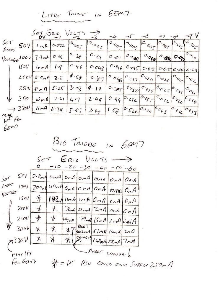
I've got 2 list of results, one for the little triode and one for the bigger triode. I'll scan and post that up before I do the graph.
Move aside Morgan Jones, there's a new kid in town.
Gotta pop out for a bit, more later.
DTB
Well well well, I learned stuff today.
I haven't done the graph yet (but I will) but today I've learn't that with the grid at 0V and the HT increasing you get hoooooge current flow but make the grid go -VE by a smidge you can control that current flow. Make it go even more -VE and you can shut the flow off. Rad. I've got it. Hence I think now understand why you bias a grid -ve and then stick a wibbly signal on top, it then makes a bigger wibbly wobbly at the anode.
I've got 2 list of results, one for the little triode and one for the bigger triode. I'll scan and post that up before I do the graph.
Move aside Morgan Jones, there's a new kid in town.
Gotta pop out for a bit, more later.
DTB
"The fat bourgeois and his doppelganger"
-
Cressy Snr
- Amstrad Tower of Power
- Posts: 10582
- Joined: Wed May 30, 2007 12:25 am
- Location: South Yorks.
#10
YepDave the bass wrote:Sorry gents, Didn't have time to post lunchtime, too busy with 3 PSU's 2 DVM's and a pencil and paper.
Well well well, I learned stuff today.
I haven't done the graph yet (but I will) but today I've learn't that with the grid at 0V and the HT increasing you get hoooooge current flow but make the grid go -VE by a smidge you can control that current flow.DTB
That's why my several of my EL509s in the OTL destroyed themselves when they lost their grid bias current.
Steve
#11
Yep, what you have there is called a diode, that why you will often see the 0v grid line called the diode line.I've learn't that with the grid at 0V and the HT increasing you get hoooooge current flow
Great, I hoped that would be the outcome. And maybe if you post the graphs, once you start to plot a loadline it will help to become a general introduction.Well well well, I learned stuff today.
Whenever an honest man discovers that he's mistaken, he will either cease to be mistaken or he will cease to be honest.
-
Dave the bass
- Amstrad Tower of Power
- Posts: 12276
- Joined: Tue May 22, 2007 4:36 pm
- Location: NW Kent, Darn Sarf innit.
#12
Its a bit messy but it makes sense to me.
I'll tackle the graph this weekend. It's Julies Birfday on Sunday and I'm taking her out for a big day tomorrow in advance, ahhhh.
Brilliant fun today discovering something.
Ta for all the guidance everyone.
DTB
EDIT. I confess I was bad to 6EM7, I made his power anodes glow a bit when I was testing, I'd forgotten the warning to keep track of the max ratings of each triode but it was one half of a pair of Sylvania's one of which did the firework impressions on warm-up so it's a donor valve anyway.
I'll be more careful with the 2 NOS GE 6GL7's that are on the way.
"The fat bourgeois and his doppelganger"
-
Dave the bass
- Amstrad Tower of Power
- Posts: 12276
- Joined: Tue May 22, 2007 4:36 pm
- Location: NW Kent, Darn Sarf innit.
#13
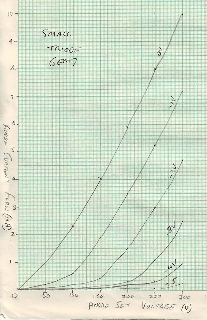
Here's the graphs. Blooming took ages (though it doesn't look like it). If you can use them on your Loadlines thread Nick please do, go ahead. I've guessed the curvature of some of the lines as theres not a lot of plot points in places. It's not easy trying to cram this sort of thing into my lunchbreak y'know 
Little Triode.
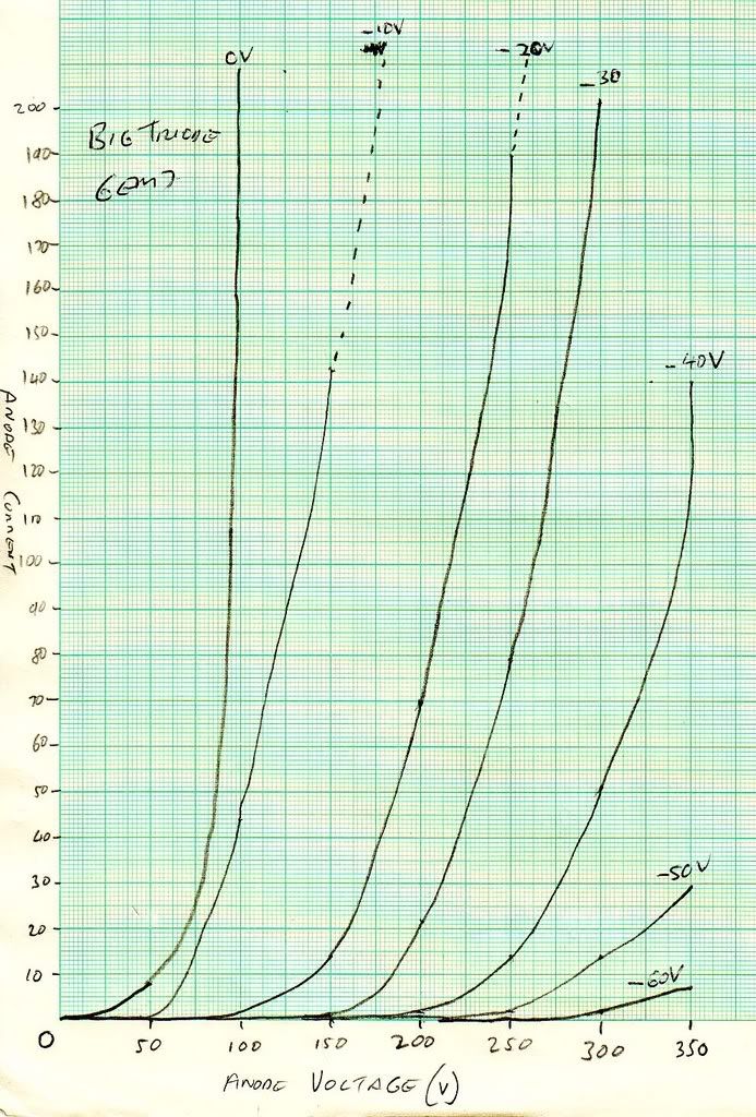
Big Triode.
I'm reading through the page that Colin linked to in your Loadline thread (the 'Bogus' cct designer URL, thats actually really helping).
Although my graphs are naff I can get the gist of the info that required, more than that having played with the 2 PSU's and a 6EM7 on the bench like I did I can see how at a certain sweet spot a tiny voltage change on the grid makes a whopping big change on the Anode current swing.
Next up for me is to get my head around how the valve thinks the grid is -ve wrt to the cathode. I can understand that when I connect the PSU's up like I did (+ve of one psu to the -VE of the other I made the cathode the OV reference and the other PSU made the grid -VE but I'm not fully understanding how the cathode resistor shifts the 0V point and makes the valve think that the Grid is -VE in a typical cct. It'll sink in eventually though don't worry.
DTB
Little Triode.
Big Triode.
I'm reading through the page that Colin linked to in your Loadline thread (the 'Bogus' cct designer URL, thats actually really helping).
Although my graphs are naff I can get the gist of the info that required, more than that having played with the 2 PSU's and a 6EM7 on the bench like I did I can see how at a certain sweet spot a tiny voltage change on the grid makes a whopping big change on the Anode current swing.
Next up for me is to get my head around how the valve thinks the grid is -ve wrt to the cathode. I can understand that when I connect the PSU's up like I did (+ve of one psu to the -VE of the other I made the cathode the OV reference and the other PSU made the grid -VE but I'm not fully understanding how the cathode resistor shifts the 0V point and makes the valve think that the Grid is -VE in a typical cct. It'll sink in eventually though don't worry.
DTB
"The fat bourgeois and his doppelganger"
#14
Nice graphs, the -10v line on the big triode looks a tad suspect, but other than that just what I would have hoped for.
So if the grid is at -10v and the cathode 0v, the grid regards itself as being 10v negative of the cathode. If the cathode is at 10000v and the grid at 9990v the grid still loogs at -10 with respect to the cathode. So (and this is the point), if the grid is at 0v and the cathode at +10v, the grid is still -10v with respect to the cathode.
Its always a potential difference, there is no official 0v, (ok earth in your mains is a good candidate), it sall in the difference.
If you were hanging off a live 500kv power line, that wire would be your 0v, and nothing bad would happen unless you went near another point at a different potential. Of course the problem you face on the live wire, is getting on and off. I think they use helicopters and wear special conductive clothing (yes, they actually do that).
All ypu need to remember is the valve only knows about the voltages and current on its pins, it has no way of knowing anything else.Next up for me is to get my head around how the valve thinks the grid is -ve wrt to the cathode.
So if the grid is at -10v and the cathode 0v, the grid regards itself as being 10v negative of the cathode. If the cathode is at 10000v and the grid at 9990v the grid still loogs at -10 with respect to the cathode. So (and this is the point), if the grid is at 0v and the cathode at +10v, the grid is still -10v with respect to the cathode.
Its always a potential difference, there is no official 0v, (ok earth in your mains is a good candidate), it sall in the difference.
If you were hanging off a live 500kv power line, that wire would be your 0v, and nothing bad would happen unless you went near another point at a different potential. Of course the problem you face on the live wire, is getting on and off. I think they use helicopters and wear special conductive clothing (yes, they actually do that).
Whenever an honest man discovers that he's mistaken, he will either cease to be mistaken or he will cease to be honest.
#15
Good explanation, Nick.
One of the best videos I ever saw and a good example of this, was how the Canadians, during lulls in serious ice storms, use a helicopter to clear the ice of power lines so the pylons don't collapse under the weight of the frozen water hanging off the lines, when the pylons go, they apparently do so domino stylee and that it no power/big repair bill.
A guy simply stood on the skids of the 'copter in harness while the pilot hovered over the live (25kv or so I assume) power line. The guy (highly paid I hope) simply bashed the ice off with what looked like a large mallet or axe. Having cleaed one phase they just moved onto the next.
Amazing....sight.
cheers,
-- Andrew