Last bit of structural work done to the arm. My back is killing me today from hoiking the lathe about over the last few days, man portable it is not. so I thought id do something that doesnt involve lifting anything. Must be getting old.....
Anyway, back to this project, ive drilled and tapped another m4 hole in the rear of the housing for some more stud to screw into. Just above the counterweight stub This piece holds the bias weight, and is on the plane of the pivot point so it doesnt affect the azimuth, stright along the cenre line of the arm. I used the stud again rather than butchering another lenco part as the thread means I have much finer control over the amount of bias applied. I might put a longer stud in if it needs it.
Also gave the tube a lick of black paint. Doesnt look so Heath Robinson now.
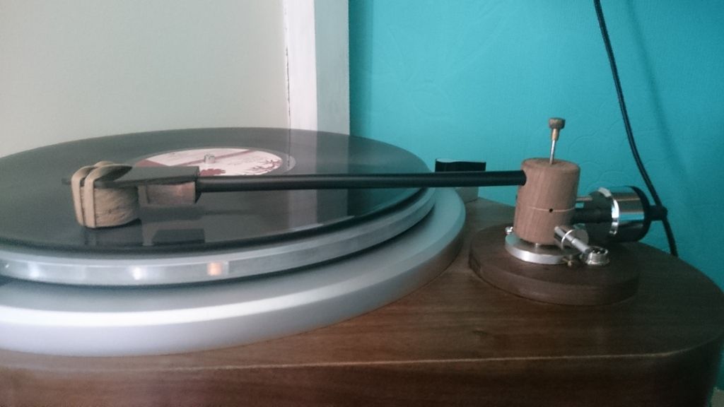
The bit of walnut attached to the headshell with the rubber band simulates a cart, it weighs 6.5g, which handily is almost the same as the shure m97xe which is 6.6g. So i can balance the arm accurately as if the cart was installed, and check the bias is working and the azimuth is unaffected by it.
Happily, this is the case


