A unipivot made from scrap
-
cressy

- Shed dweller
- Posts: 2906
- Joined: Fri Aug 03, 2007 7:07 pm
- Location: the great white space
- Contact:
#61 Re: A unipivot made from scrap
Also need to add a bias mechanism, twisting the wiring isnt adding enough. String and weight will do

#62 Re: A unipivot made from scrap
If this has been answered, apologies, but with a Formula IV, one swivels the counterweight to get the pivot housing true and vertical, the needle point can be fine tuned for height and a little fluid was usually added for a small amount of damping* - just enough to stop excessive wobble a la Naim ARO (if anyone's seen one in use). I never thought this arm was rigid enough for any low compliance moving coil types, unlike the Hadcock, which had other construction issues, but the Formula IV was superb with high compliance ADC's and Sonus models for example, so today, one of the more delicate AT's of either persuasion should be great possibly.
I seem to remember the groove for the bias thread was in line with the pivot point, but as said below, these are very old memories once instinctive as I set so many up.
* Forty years ago now, but I seem to remember just covering the tapered part of the bearing well with fluid and not filling to the brim.
-
IslandPink

- Amstrad Tower of Power
- Posts: 10041
- Joined: Tue May 29, 2007 7:01 pm
- Location: Denbigh, N.Wales
#63 Re: A unipivot made from scrap
The azimuth should be set as close as possible by loosening a small screw on the headshell collar and aligning that to the housing. Once mounted on the pivot azimuth can be fine-tuned using the eccentric counterweight, as you say. The groove for the bias actually has to be adjusted to be in line with the pivot point as well. The pivot point is mounted through the Perspex top part with a thread and a locknut. You have to sight carefully through the side of the top housing to get the point in line with the groove. I only realised this about 5 years ago, although it was close enough thankfully.
As standard I can believe it works very well with high-compliance carts. My experience of adding weight to the headshell and an extra counterweight was also entirely positive when used with the 103R. My previous two arms for the 103R were an SME 3012 II and the Mk.2 OL Illustrious. The Mayware has better tone, especially in the treble and with a non-SUT phono proved itself to be extremely good in the low bass despite the thin wand. It's not a very rigid arm overall, but I think the key thing when you put mass on the headshell is that the bass notes are working against the inertia of the headshell, it's not relying on having to work against the counterweight via the wand.
As standard I can believe it works very well with high-compliance carts. My experience of adding weight to the headshell and an extra counterweight was also entirely positive when used with the 103R. My previous two arms for the 103R were an SME 3012 II and the Mk.2 OL Illustrious. The Mayware has better tone, especially in the treble and with a non-SUT phono proved itself to be extremely good in the low bass despite the thin wand. It's not a very rigid arm overall, but I think the key thing when you put mass on the headshell is that the bass notes are working against the inertia of the headshell, it's not relying on having to work against the counterweight via the wand.
"Once you find out ... the Circumstances ; then you can go out"
#64 Re: A unipivot made from scrap
The arm used to come with the Perspex top piece unscrewed and removed, so it was easy to set the pivot depth before screwing the Perspex top piece on (forgive lack of terminology). Headshell azimuth was done when fitting and overall-alignment of the cartridge and I don't remember it being difficult to do. The manufacturers used to supply a kit of tiny Allen keys for different parts of the arm as well as a tube of damping fluid - I can't remember how thick this fluid is and although it's the same as the viscous silicon stuff used in cueing device cylinders, the thickness varies from arm to arm - I think Dual use 100,000, but other arms need 300,000 or 500,000 thickness and this might be too thick for the Mayware pivot.
Gerald Bearman (spelling?) who imported the Mayware was around not too many years ago and may still be contactable for any expert advice needed.
Gerald Bearman (spelling?) who imported the Mayware was around not too many years ago and may still be contactable for any expert advice needed.
-
Cressy Snr

- Amstrad Tower of Power
- Posts: 10581
- Joined: Wed May 30, 2007 12:25 am
- Location: South Yorks.
#65 Re: A unipivot made from scrap
I use 60,000cS fluid in my Mayware pivot. I tried 100,000cS but it killed the life.
60,000 is perfect.
60,000 is perfect.
Sgt. Baker started talkin’ with a Bullhorn in his hand.
-
cressy
- Shed dweller
- Posts: 2906
- Joined: Fri Aug 03, 2007 7:07 pm
- Location: the great white space
- Contact:
#66 Re: A unipivot made from scrap
Interesting that you mention the extra weight at the headshell end has an effect on bass tone mark,
Hmmmm
Hmmmm
-
cressy
- Shed dweller
- Posts: 2906
- Joined: Fri Aug 03, 2007 7:07 pm
- Location: the great white space
- Contact:
#67 Re: A unipivot made from scrap
Made some time between jobs to make a start on the mk 2 version. Made the headshell and tube part.
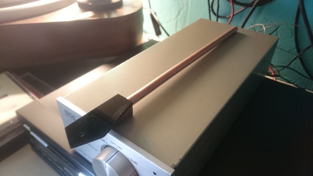
I used the same materials as before to keep continuity between versions, and to make sure im not adding in something to the sound it makes by changing materials. I want to make sure that the design refinements are what makes a difference, and to stay on track. So i wont be modifying the wands once ive made them, rather make another one to try refinements.
With this one ive made the headshell much lower wrt the arm tube to bring the moving mass much closer to the stylus. It will be give or take half an inch lower to try to make it less likely to rock and to stabilize quicker.
Following marks comment that the extra weight on his mayware to make it work better with a 103 has an influence on the bass, i have used a walnut block again as part of the mounting. Its about 2 3rds the size of the mk 1 and keeps a concentration of mass around the cart, but behind it rather than above.
I'll need to turn a new housing as the mk1 housing will be too tall. I could use it as the wands are detachable, and the pillar will go low enough, but it will put the c/w stub about 12mm lower too.
I also want to add a string and weight bias arrangement, and the mayware arrangement is ideal for what i want to do, so I will cut a groove for the line to run in, and add a small inspection hole in the groove so i can see the bearing needle. That was i can make sure that the bias weight runs on the same plane as the pivot and doesnt affect the azimuth
Thats the plan anyway
-
IslandPink
- Amstrad Tower of Power
- Posts: 10041
- Joined: Tue May 29, 2007 7:01 pm
- Location: Denbigh, N.Wales
#68 Re: A unipivot made from scrap
Ooh cripes ! Did you not know this ? - you've never looked carefully at James's Kenwood decks at Owston with the 50p piece on the headshell, then ?
edit : looks like the latest mods are going in a nice direction. Ebony can be had for not too much money for another build, btw. I have a stash and one day
"Once you find out ... the Circumstances ; then you can go out"
-
cressy
- Shed dweller
- Posts: 2906
- Joined: Fri Aug 03, 2007 7:07 pm
- Location: the great white space
- Contact:
#69 Re: A unipivot made from scrap
I just thought it was in just relation to making a 103 work in light arms. Im not really a 103 fan tbh, eosd drives me up the wall, ive never managed to get rid of it when using one. maybe if I had one that had an elliptical stylus or something i might be more of a fan.
#70 Re: A unipivot made from scrap
A 103 in a Formula IV? I'd never have done it as I'd assume the arm was too light and too resonant for such an old-timer cartridge designed for heavyweight tonearms (look up the huge Gray tonearm for inspiration)..
http://audiokarma.org/forums/index.php? ... es.408120/
Cressy, have you thought of adapting the tube-headshell for a lenco L75 pipe/bearing arrangement? I got the feeling that the bearing block on an L75 arm was ok, but if a V bearing shaft could be drifted in at the right place through the tube, a one-piece tonearm may make for an improvement...
My memories of the 103 are that in a suitable arm, end of side effects are a dullness due to the physics of the conical tip rather than distortion, but it was a long time ago and the only one I owned was the differently compromised 103D which was different altogether.
#71 Re: A unipivot made from scrap
Ahhhh... That Gray is MY old tonearm. I sold that to Nate (RedBoy) a good few years ago. Worked really well with a 103 on my GL88... What a blast from the past !! 
©2020 Lee
-
cressy
- Shed dweller
- Posts: 2906
- Joined: Fri Aug 03, 2007 7:07 pm
- Location: the great white space
- Contact:
#72 Re: A unipivot made from scrap
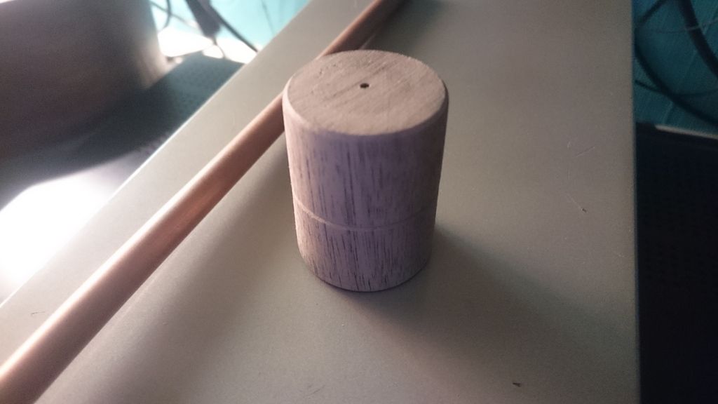
While the lathe was out I spun up a new housing for the mk 2. With a groove for a bias mechanism

-
cressy
- Shed dweller
- Posts: 2906
- Joined: Fri Aug 03, 2007 7:07 pm
- Location: the great white space
- Contact:
#73 Re: A unipivot made from scrap
Made some progress with the mk 2 today, got the housing drilled out for the tube and stub, and drilled the tube out for the bearing pin. Again set to an effective length of 237mm a la rb250.
This time I have decided to address another issue with the mk 1, namely the absolute swine it is to set up.
The problem being that both tracking weight and azimuth are set bt the lenco counterweight, and it was a complete pig to set one without altering the other.
To this end ive decided to separate the 2. Ive dug out another counterweight which isnt dropped and weighs pretty much the same as the lenco counterweight. Dunno what it came off but it's only 3g heavier than the lenco so is handily close. It is also not as deep as the lenco one is so its centre of mass will be slightly closer in to the pivot too.
The groove in the housing is where the pivot is and is less than 1mm above the plane the stylus will be at. The centreline of the stub is 7mm below this line so the centre of gravity of the arm will be just below the pivot point.
So far it ticks the appropriate boxes.
In order to set the azimuth I will be adding an m4 threaded outrigger to the right hand side of the arm that will have a thumb nut on it. This will be below the plane of the stub to lower the c/g a little more as the mass of the cart and headshell will be above the pivot point. Screwing it in or out will alter the azimuth. I might need to put one on both sides, depends on what it does.
There is a small inspection hole so the bearing point can be seen and set, but ive still got to add a small copper bar for the bias weight to attach to. For some reason I dont seem to have a 1 mm drill bit to do it right now.....
So loads to do still
Last edited by cressy on Thu May 04, 2017 7:22 pm, edited 1 time in total.
-
Dave the bass

- Amstrad Tower of Power
- Posts: 12276
- Joined: Tue May 22, 2007 4:36 pm
- Location: NW Kent, Darn Sarf innit.
#74 Re: A unipivot made from scrap
I liked my Decca Unipivots but setting Azimuth was trixxy on one of them.
The other had this clever 'weight-within-a-weight' adjuster that made it a lot easier. Could you make anything like this Ant?
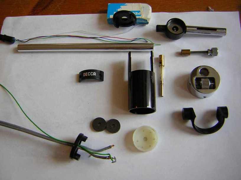
See how the chromed counterweight has a knurled centrepiece that you can wind left or right? Thats what shifted the azimuth, clever innits.
The other had this clever 'weight-within-a-weight' adjuster that made it a lot easier. Could you make anything like this Ant?
See how the chromed counterweight has a knurled centrepiece that you can wind left or right? Thats what shifted the azimuth, clever innits.
"The fat bourgeois and his doppelganger"
-
cressy
- Shed dweller
- Posts: 2906
- Joined: Fri Aug 03, 2007 7:07 pm
- Location: the great white space
- Contact:
#75 Re: A unipivot made from scrap
I had one of those a few years ago too dave, twas a great arm, wish I still had it.
I have thought about making something of that ilk, but my metal lathe wot I got off our very own Mr sheils is still sans a chuck, and wants a more powerful motor before it it can turn steel.
Wish I could afford this but it'll go for really good money
http://www.ebay.co.uk/itm/162495099649
It'd be perfect for me