To me it looks like the upper triode is providing a highish load by multiplying its cathode resistor. And the lower valve is just being a common cathode amplifier with a unbipassed cathode resistor. So I think the lower valve will set the bulk of the output impedance, so the normal
rout = ra + ( µ + 1 ) Rk
should apply.
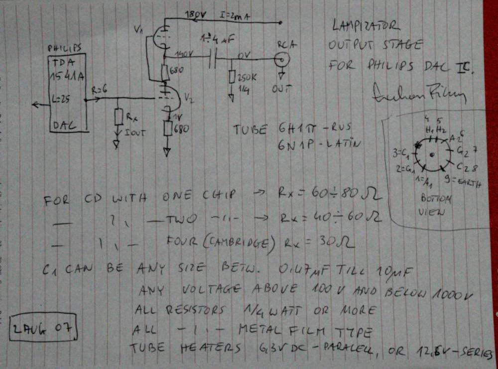
Lampy cd player
#17
Hi Nick,
Yes, agreed exactly except that if the top triode is a cathode follower it will have a low impedance and dominate the lower valve impedance.
looking up into the cathode of the top triode is,
(rk+ra)/(µ+1)
I haven't got ra so will take it as ecc83 at 65k,
(0.2+65)/100+1) = 0.645K
and that would be the plate load for the bottom triode (effectively multiplied the top Rk as you say)
Looking down into the bottom triode is,
ra + ( µ + 1 ) Rk as you say also,
65+((100+1)x0.2) = 85K2
and that would be the cathode load for the top triode,
which would make the op impedance,
0.645K//85K2 = 640R
If that's right it's very neat and a lot better than many comments I've seen about it around the web though I don't know what the rest of the operating conditionas are for that valve with 645R load and 200R cathode resistor. It's getting late so I've probably missed something important what do you think?
Yes, agreed exactly except that if the top triode is a cathode follower it will have a low impedance and dominate the lower valve impedance.
looking up into the cathode of the top triode is,
(rk+ra)/(µ+1)
I haven't got ra so will take it as ecc83 at 65k,
(0.2+65)/100+1) = 0.645K
and that would be the plate load for the bottom triode (effectively multiplied the top Rk as you say)
Looking down into the bottom triode is,
ra + ( µ + 1 ) Rk as you say also,
65+((100+1)x0.2) = 85K2
and that would be the cathode load for the top triode,
which would make the op impedance,
0.645K//85K2 = 640R
If that's right it's very neat and a lot better than many comments I've seen about it around the web though I don't know what the rest of the operating conditionas are for that valve with 645R load and 200R cathode resistor. It's getting late so I've probably missed something important
#18
Yes, but I think there is one fault in that logic. First, I agree that the top valve looks like a cathode follower, BUT the signal is not being taken from the cathode, but effectively from the grid. So I think all you can say about the top triode is that it is multiplying the cathode resistor up and starting to emulate a CCS. The effective resistance of the top triode is
rt = Rk / ( 1 - µcf )
where µcf is the gain of the cathode follower
µcf = µ / ( 1 + µ )
so for a 220 cathode resistor and gain of 100 we have
220 / ( 1 - ( 100 / 101 )) = 22k
So the lower triode has a anode load of 22k
Then as you say, the lower triode is a common cathode amp with a unbypassed cathode. So as you say the ra is 85k, so the output impedance at the lower triode anode is
22k || 85k or 17k
It would be a different matter if the output was from the upper cathode. But then you have the upper valve loaded with 220R, which is far to low a value for that valve, so the distortion spectra would be poor (which is why I suspect the output is taken from the lower anode), so to increase the load the top triode sees you start to consider increasing the resistor in its cathode. and then you eventually find yourself at the µ follower. Or using a CCS in the cathode of the upper valve. But then you consider the fact that the load is in parallel with the cathode load of the top valve, so making its load large by a CCS or µ follower fails when a real load is applied across the output. Or more to the point (pun intended) a complex load.
IMHO, the circuit you are building would be better is the upper triode was removed and just replaced with a CCS.
Whenever an honest man discovers that he's mistaken, he will either cease to be mistaken or he will cease to be honest.
#19
Thanks Nick,
The position of the output was troubling me for a while but I think it doesn't affect the top triode being a cathode follower. It just puts the top 200R in series with the cathode output which is a good thing anyway (and a small attenuation).
The top triode grid is driven from the anode of the bottom triode (which is providing voltage gain) but I think the output current will be from the cathode of the top triode (and the anode of the bottom triode I suppose as they are both the same phase wise).
Would you have a look here and see if you agree with how I read it; that taking the output from under the top 200R makes little difference, start of second para where he leaves out the word "not" by mistake I think, and again, penultimate para right at the bottom of the page,
http://www.freewebs.com/valvewizard/accf.html
#20
I think that it does make a difference, because below the cathode any change in voltage is not seen by the grid of the top triode so the feedback action does not work to counter it.
Consider the condition with the output unloaded, lets say the valves are passing 10ma, so the two cathode resistors have 2v on them, so each triodes grid is -2v.
Now lets apply a 10k load to the anode of the bottom valve. Before the load is applied. the voltage on the lower anode is half B+ or 75v. Because the upper triode will act to try and maintain 2v across its cathode resistor the only way it can do that is to increase the voltage across the upper triode, which means the voltage across the lower triode reduces, until the lower triode and the 10k are passing the 10ma between them. So the voltage on the lower anode will reduce to say 45v, so say 4.5ma will pass trough the load, and 5,5ma will now pass through the lower triode.
So applying a 10k load will have (with made up but I think representive numbers) caused the voltage on the output to fall from 75v to 45v
Now do the same thing with the 10k load above the cathode resistor on the top triode. you gave 75+2v at that point, so the current through the load will be 7.7ma, so the current through the top valve will now be 17.7ma, as the current through the cathoide resistor will say the same, so the voltage on its grid will stay the same, so the increase of 7.7ma through the top triode will increase the voltage dropped across the triode by 7.7ma / gm. The current through the cathode resistor will remain about the same, the voltage on the top triode grid will remain about the same, the voltage on the lower anode will change by the same 7.7ma / gm.
So the overall effect of adding a 10k load above the cathode resistor is to cause the output voltage to only change by the load current divided by gm.
So we can see that applying the same load to the two points causes two very different changes in voltage across the load. So we can see that the impedance of the current source supplying the load are very different in the two cases.
Whenever an honest man discovers that he's mistaken, he will either cease to be mistaken or he will cease to be honest.
#21
Hi Nick,
Fantastic, thanks for taking the trouble to explain so well
So under quiescent dc conditions it would all look reasonable and measure at one set of voltages (due to the output cap) but under ac the load, "active cathode resistor" and "non compensating cathode follower" (can we allow those descriptions? ) become an issue, if only to move the balance point?
Does this make a difference though, if the load is known and accounted for, other than shifting the balance point and making a nonsense of my figures?
Presumably a higher load would be better and as it is fixed ('ish as my pot is a shunt pot varying 50K - 100K region) and known it will still work in a linear way and can be factored in to set the conditions.
It's built now so I'll give it a go at least. I can see how it might give different results depending on the preamp load though.
This is new territory and I take on board your ccs suggestion. Is there an easy way to implement it, or use the top triode differently? A quick look at srpp shows load is to be factored in too. Thanks again.
Fantastic, thanks for taking the trouble to explain so well
So under quiescent dc conditions it would all look reasonable and measure at one set of voltages (due to the output cap) but under ac the load, "active cathode resistor" and "non compensating cathode follower" (can we allow those descriptions?
Does this make a difference though, if the load is known and accounted for, other than shifting the balance point and making a nonsense of my figures?
Presumably a higher load would be better and as it is fixed ('ish as my pot is a shunt pot varying 50K - 100K region) and known it will still work in a linear way and can be factored in to set the conditions.
It's built now so I'll give it a go at least. I can see how it might give different results depending on the preamp load though.
This is new territory and I take on board your ccs suggestion. Is there an easy way to implement it, or use the top triode differently? A quick look at srpp shows load is to be factored in too. Thanks again.
#22
Ah, you may have missed part of my point. The change in the voltage level upon the application of a load is the direct result of the differing source impedance at those two point. By showing that the same load applied at the two points leads to two differing voltage shifts indicates that the source impedance at those two points are far from the same value as you were asserting.
Yep, the big problem with SRPP is it is very intolerant of load.
Simple way of implementing a CCS as a anode load would be a C4S CCS, I am sure someone has a link to one on hand. Basically two tramsistors, two LED's and a couple of resistors.
Yep, the big problem with SRPP is it is very intolerant of load.
Simple way of implementing a CCS as a anode load would be a C4S CCS, I am sure someone has a link to one on hand. Basically two tramsistors, two LED's and a couple of resistors.
Whenever an honest man discovers that he's mistaken, he will either cease to be mistaken or he will cease to be honest.
#23
Yes, quite likely, I get most of it but wasn't looking at it quite that way, it will fall into place over the next 10 years
I'll work it through it again and at least know how to work it out and what to look out for when I need it, brilliant thanks
Using the ccs I'd then choose conditions and redoe the bottom triode as a simple anode output presumably? Does the ccs have very low impedance and therefore lower the overall output impedance? (showing I've never even looked at it now but I will).
What about using that top triode at all, or is it just mu follower, srpp, or this, what would you call this, can it be improved or would that be down to redesigning it for a known load?
#24
Well, the CCS has a high impedance, thats what makes the triode its loading more linear. It doesnt help the output impedance which is just the ra of the valve unless you get cunning and use the mu output of the CCS, which is effectivly what you have with the top triode when you take the output from the top of the cathode resistor. But because the SS device has a higher gm, the output impediance is that much lower.
I would build it as shown, people have built it and like it, and I would try taking the output from the bottom and top of the resistor and pick what you prefer.
As to what else you could try. Depends on if you need gain or not I suppose.
I would build it as shown, people have built it and like it, and I would try taking the output from the bottom and top of the resistor and pick what you prefer.
As to what else you could try. Depends on if you need gain or not I suppose.
Whenever an honest man discovers that he's mistaken, he will either cease to be mistaken or he will cease to be honest.
-
Mike H

- Amstrad Tower of Power
- Posts: 20189
- Joined: Sat Oct 04, 2008 5:38 pm
- Location: The Fens
- Contact:
#25
Anything wrong with tacking a CF onto the output of the SRPP? Apart from that it's yet one more valve to accommodate
"No matter how fast light travels it finds that the darkness has always got there first, and is waiting for it."
#26
No, I guess not, but using the second triode as a simple CF, and loading the first anode and the CF with a CCS each would possibly be the best of both worlds.
Whenever an honest man discovers that he's mistaken, he will either cease to be mistaken or he will cease to be honest.
#27
I was thinking exactly that, separating the 2 sections, giving them their own loads, reconfiguring as a common cathode amp followed by a cathode follower even without ccs. Of course we can go on forever and I suppose using 2 different valve types may be better still etc. I'll stick to plan A then to Thorstens or Lampys 6n1 which are both srpp,
http://www.fortunecity.com/rivendell/xe ... asfda.html
http://www.fortunecity.com/rivendell/xe ... ltibit.gif
http://www.lampizator.eu/LAMPIZATOR/TDA ... %20003.jpg
http://www.fortunecity.com/rivendell/xe ... asfda.html
http://www.fortunecity.com/rivendell/xe ... ltibit.gif
http://www.lampizator.eu/LAMPIZATOR/TDA ... %20003.jpg
#28
Hi Nick, as there is a output coupling cap there will be no loading at dc so how would we check/calc the ac conditions? (It was that bit still in my mind when I said it would take a while to settle in!) Could we dc connect a 50K (say) load and re-check voltages empirically to find the real setting and would that then be valid for (almost) all ac conditions?Nick wrote:Ah, you may have missed part of my point. The change in the voltage level upon the application of a load is the direct result of the differing source impedance at those two point. By showing that the same load applied at the two points leads to two differing voltage shifts indicates that the source impedance at those two points are far from the same value as you were asserting.
Yep, the big problem with SRPP is it is very intolerant of load.
Simple way of implementing a CCS as a anode load would be a C4S CCS, I am sure someone has a link to one on hand. Basically two tramsistors, two LED's and a couple of resistors.
I'm hoping to have it finished today and have run it last night without op coupling caps.
The check was a little surprising. I've got 174V at the top anode but the drop across the last psu resistor on each side is 13V across 10K so only 1.3mA flowing through both sections. I'd have expected more, any thoughts? Thanks.
#29
yes, AFAIKS there are no AC only paths in the circuit before the coupling cap, so (as in my written 10k example) the shift in DC conditions from applying a resistor to the output is equivalent to applying a load through a cap.Hi Nick, as there is a output coupling cap there will be no loading at dc so how would we check/calc the ac conditions? (It was that bit still in my mind when I said it would take a while to settle in!) Could we dc connect a 50K (say) load and re-check voltages empirically to find the real setting and would that then be valid for (almost) all ac conditions?
In fact the better check, would be open output. 50k resistor from output to gnd, then the same resistor to b+, so not only can you check the output impedance, you can also check the output is symmetric.
As to the current, I would have to draw the load lines for the triodes you have used.
Whenever an honest man discovers that he's mistaken, he will either cease to be mistaken or he will cease to be honest.
#30
Thanks, this is why my stuff takes so long, I have to know what's going on
I'll have a cup of tea then do as you suggest. First part I understand output>50K>ground and was going to try that anyway.
Second part; op>50K>B+, any particular part? the anode of the top valve or earlier (sorry, at this stage I don't understand the purpose and can see there are droppers in the B+ line).
I'll lift the valve holder to get the voltages for both sections open output, then with the load to see what changes. Anything in partic we need to check?