Yes, thank you for interjecting. I had the resistor in there. What I was going to do was one resistor and the pot, which would be switched and turned round between minus rail and earth or plus rail and earth depending on the output valve. I just chose the value for ease of decision, it may not travel to it's greatest extent.
I either need positive bias or negative bias, but I don't envisage an output valve for which I would need both.
I thought I would just put a simple ecc83 RC gain stage on the board I am making up. May not be the best preamp ever invented, but all that's needed in front of this is voltage gain. At a later date it could be made exotic. It would be interesting to see how it sounds simple. I would borrow from the 450v supply for it.
811a SET amp.
-
Paul Barker

- Social Sevices have been notified
- Posts: 8980
- Joined: Mon May 21, 2007 9:42 pm
#196
"Two things are infinite, the universe and human stupidity, and I am not yet completely sure about the universe." – Albert Einstein
-
Paul Barker
- Social Sevices have been notified
- Posts: 8980
- Joined: Mon May 21, 2007 9:42 pm
#197
My parts arrived.
I haven't a clue when I will find the time to assemble them
I haven't a clue when I will find the time to assemble them
"Two things are infinite, the universe and human stupidity, and I am not yet completely sure about the universe." – Albert Einstein
-
Paul Barker
- Social Sevices have been notified
- Posts: 8980
- Joined: Mon May 21, 2007 9:42 pm
#198
I'll carry this on here though it sort of has more relevance on my 572-160 thread.
Stephie adapted the 841 A2 design to 572-160. The results of which we can draw from with some hope.
You will see from the link that the distortion components maintain a relativity right across the power range, 2nd holding top place throughout. At the max power of 8 watts 2nd is -28db (4%) and at 1 watt - -37.5 db (1.33%). Whether the fact the various components hold to a similar respective position most of the time will result in a realism of timbre could translate from a hopeful hypothesis into a highly satisfactory outcome is yet to be revealed.
The operating point of +13v 490v 40mA seems quite attainable. 8 watts is plenty for my plans and keeping the voltage down is more in keeping with my present situation.
With a 400v transformer of enough current (in my case 625mA) a single 6080 pass reg could feed the 450v to two channels and another the 490v to the output stage (1/2 a 6080 per channel).
I will probably heat the ac valves ac and most likely the current hungry 572-160 filament ac as well, care of another Stephie method that I have tried on the 6b4g with great success.
With respect to the voltage bias setting divider at the front of the acf2 which sets the +13v, I shall check this out before posting up the schematic, as I am a little sketchy about whether to devise from B+ to B- or from B+ to ground or B- to ground depending where one of the ends is positioned, and comparing this to a zero bias no intervention version.
Oh sh1te there goes my alarm, it's off to work!
"Two things are infinite, the universe and human stupidity, and I am not yet completely sure about the universe." – Albert Einstein
-
IslandPink

- Amstrad Tower of Power
- Posts: 10041
- Joined: Tue May 29, 2007 7:01 pm
- Location: Denbigh, N.Wales
#199
That...
http://diyaudioprojects.com/mirror/memb ... part2.html
..is a clever design - well impressed !
Thanks for reminding me of that . So, the second 8532 must be low imedance at AC when used like that ?
http://diyaudioprojects.com/mirror/memb ... part2.html
..is a clever design - well impressed !
Thanks for reminding me of that . So, the second 8532 must be low imedance at AC when used like that ?
"Once you find out ... the Circumstances ; then you can go out"
-
Paul Barker
- Social Sevices have been notified
- Posts: 8980
- Joined: Mon May 21, 2007 9:42 pm
#200
I think it's just to pull current through the bias resistor so it can reduce sufficiently in value so desired gain is achieved.
Not to mention the means of level shifting could be adapted to ACF2 circuit. I have enough on my plate for now.
Not to mention the means of level shifting could be adapted to ACF2 circuit. I have enough on my plate for now.
"Two things are infinite, the universe and human stupidity, and I am not yet completely sure about the universe." – Albert Einstein
-
Paul Barker
- Social Sevices have been notified
- Posts: 8980
- Joined: Mon May 21, 2007 9:42 pm
#201
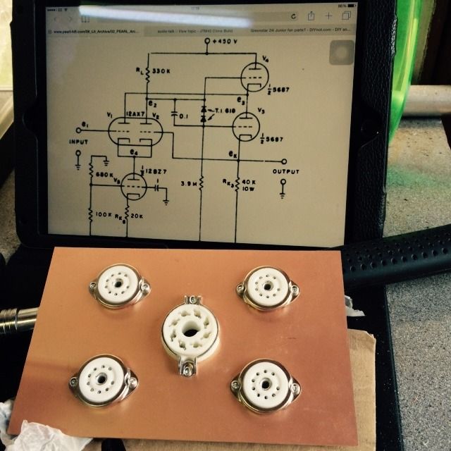
I made a start. Accidentally mounted 9 pin bases for the output valves, so plan has changed to 5687 from 6bx7.
Decided to build the ACF2 mudule in such a way as it can plug into any preamp and power any output valve.
A long way to go yet.
Decided to build the ACF2 mudule in such a way as it can plug into any preamp and power any output valve.
A long way to go yet.
"Two things are infinite, the universe and human stupidity, and I am not yet completely sure about the universe." – Albert Einstein
-
andrew Ivimey

- Social Sevices have been notified
- Posts: 8318
- Joined: Mon Jun 11, 2007 8:33 am
- Location: Bedford
#202
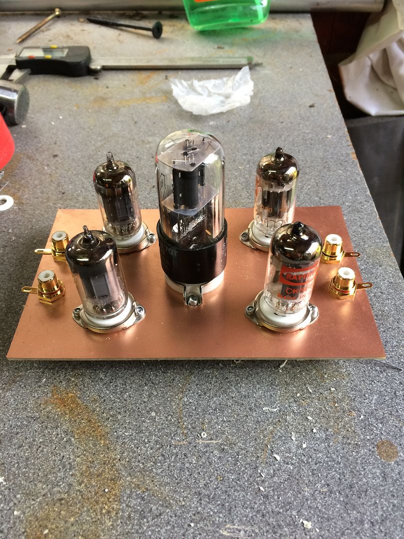
Very neat & tidy! Nowt wrong with a 5687...
Philosophers have only interpreted the world - the point, however, is to change it. No it isn't ... maybe we should leave it alone for a while.
-
Paul Barker
- Social Sevices have been notified
- Posts: 8980
- Joined: Mon May 21, 2007 9:42 pm
#203
Thanks Andrew. It was just like most things I do these days, half a mind somewhere else, just picked up the board opened up the picture layer out the valves as per the ones in the picture, except I did remember about the 6sl7.
The half 6sl7 is a approximation of what is required, the difference I can make up by adjusting the resistor value on test. It will do the job.
The power supply just for this is also going to look stupidly large and heavy, so I may replan that. But there again since it is so over spec. (400v ac at 625mA) I have the luxury of shunt regulating it rather than series as I originally proposed.
Regarding the 5687's , agree, and the article does claim cosiderable peak drive current from them which should suffice for any valve I would task it with.
"Two things are infinite, the universe and human stupidity, and I am not yet completely sure about the universe." – Albert Einstein
#204
Just remember the tail of that LTP is the centre of the circuit, so making it as long as possible is essential to getting the best out of the circuit. The 6sl7 has only 70% of the gain of a 12bz7.
Last edited by Nick on Sun May 31, 2015 6:41 pm, edited 1 time in total.
Whenever an honest man discovers that he's mistaken, he will either cease to be mistaken or he will cease to be honest.
-
Paul Barker
- Social Sevices have been notified
- Posts: 8980
- Joined: Mon May 21, 2007 9:42 pm
#205
Thanks for the tip. I'll act on it!
"Two things are infinite, the universe and human stupidity, and I am not yet completely sure about the universe." – Albert Einstein
#206
If you want to try a simple SS CCS let me know and I will put a couple of 1000v depletion mosfets in the post to you.
Whenever an honest man discovers that he's mistaken, he will either cease to be mistaken or he will cease to be honest.
-
Paul Barker
- Social Sevices have been notified
- Posts: 8980
- Joined: Mon May 21, 2007 9:42 pm
#207
Thank you, the question is do they work down at 2.5 mA? As long as they do, yes that would be the best idea for the moment.
"Two things are infinite, the universe and human stupidity, and I am not yet completely sure about the universe." – Albert Einstein
#208
Good point, no, they run out of steam at about 4.5ma.
Maybe use the 6sl7 with one of these in its cathode set to 2.5ma
http://docs-europe.electrocomponents.co ... 39dfcf.pdf
Maybe use the 6sl7 with one of these in its cathode set to 2.5ma
http://docs-europe.electrocomponents.co ... 39dfcf.pdf
Whenever an honest man discovers that he's mistaken, he will either cease to be mistaken or he will cease to be honest.
-
Paul Barker
- Social Sevices have been notified
- Posts: 8980
- Joined: Mon May 21, 2007 9:42 pm
#209
Thank you Nick. I found and ordered 234-6 from RS. The 6 is limited to 30v but that shouldn't matter.
Question
I am assuming that V5 quiescent point nominally puts the anode at ground so in the original circuit v5 sees 350v.
So what I propose is put a 40k resistor in the cathode with the ccs to consume voltage, the dissipation .75 watts and the anode voltage within the limit of 300v. Does that make sense to you?
"Two things are infinite, the universe and human stupidity, and I am not yet completely sure about the universe." – Albert Einstein
#210
Ok, what I was thinking original was to use the CCS in the cathode of the 6sl7 then let the valve do the heavy lifting. I would be tempted to put a 30v zener across the current source to avoid it seeing 300v at start-up when there is no current passing.
Yes, the anode will be at a volt or so above whatever is on the input of the ACF. So you will see the signal voltage at the anode as well.
Yes, the anode will be at a volt or so above whatever is on the input of the ACF. So you will see the signal voltage at the anode as well.
Whenever an honest man discovers that he's mistaken, he will either cease to be mistaken or he will cease to be honest.