I think I mentioned that life is full of unfinished projects at the mo.....
well....
I've just discovered this in an ice cream tub in the corner of the work room....the boards were made 12 months ago but not stuffed..and there it stayed.
On revisiting I tried to understand what I'd done and realised a senior moment had resulted in some major oversight...to wit I'd fed back the amplified ac signal to the cpu thinking I would just measure the value.....all well and good but the anticipated level would overcook the input as I hadn't included a divider on the board and on further thought the assumption that the ac signal would be perfect enough to just measure one side/polarity was just that, an assumption.
also the repeated measurement of an ac signal is nowhere near as accurate as an ac to rms chip so all in all that pcb was trash.
so I reworked with an RMS to DC chip with a divider.
Now the question......
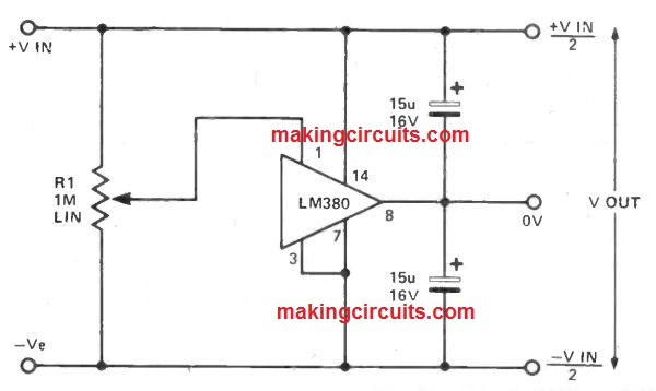
I just love the splitter circuit:

- bal_ps.jpg (60.84 KiB) Viewed 7211 times
but how to take off the 5v for the cpu?. If I put a 7805 in 1 leg of the 9v/12v supply it unbalances the feed to the opamp, which leads to distortion in the signal amplification.
Can anybody suggest how to take 5v in isolation off the 18/24v smps before it gets to the splitter circuit?
ironically I don't need a signal generator as the existing one works perfectly, it's just an unfinished project and a challenge to sort out my stupid error.