#16 Re: information needed about low power amp topology
Posted: Mon Sep 17, 2018 2:05 pm
The place to discuss anything involving sound
https://audio-talk.co.uk/phpBB3/
There's a gent on another forum who won't be pressing your button Mike!
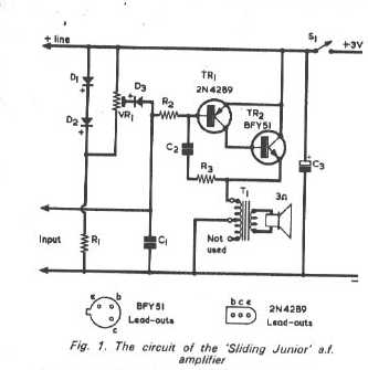
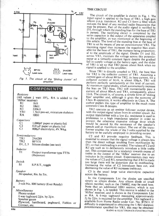
Well, don't that make you wanna build it, and see Hu? I particularly like the comment "sound quality is hand held transistor radio." Well yeah, that's kinda what I'm building!Man from Chicago wrote: It's actually high gain PNP driving a NPN emitter follower. I spent more time on this circuit since it's a sliding bias that I am interested. The problems I mentioned still stand. This is my analysis:
What the circuit tries to do is to vary the current through the transformer according to the input signal. The larger the signal, the higher the current through the transformer to keep it in class A. But this is where the problem begin:
1) in order to vary the DC current through the transformer according to the signal, you need to drive the base of TR2 more positive with the amplitude of the signal.
2) Somehow, a voltage is set up across C2 which is the integrate capacitor that control the sliding bias.
3) D1 and D2 set up +1.6V for VR1. The circuit has to be ACV coupled. When the signal first goes positive, D3 turns on, the output see lower resistance of parallel of VR1 and R1 which is 1K//1.5K = 600ohm. This load down the positive going signal and clip the positive part of the signal.
4) When the negative half of the input signal. D3 turns off, C2 is discharged through R2. So the voltage across C2 decrease. This make the voltage at the emitter of TR2 increase, thereby increase the current through the transformer T1. This will increase the bias and keep the amp in class A. When the signal goes away, C2 charge back up through D3 and R2 and VR1.
Now, ignore the concerns I have in the last post. Just assume it all work. Still, in order for this circuit to work, the output impedance has to be high, so it will clip by the sliding bias circuit on the positive half of the signal. But the impedance through C2 and R3 can load the of the driving stage down.
You need an output transformer to block the DC current. That is one more component that is more expensive than transistors. Also, the big point of transistor amp is to do away with the output transformer that not only limit the frequency response, it also create more distortion.
You might get away with two transistors, but you end up having a more expensive circuit, sound quality is hand held transistor radio at best. Using transformer is so so old!!!
The circuit is so badly design, you have to tweak and tweak to get it to work. I bet when room temperature change, it will go hey wired.
I don't know about the author, but like Raj telling Sheldon in Big Bang Theory " Not all the stuffs come out of you are gold, some are GAGA!!!". This is engineering, it's science. You can analyze the circuit. Looks like some kid wiring it up in the garage.
Mike.
Ah! Right, thanks. And Nick.Ami wrote: ↑Wed Sep 19, 2018 12:00 am Mike.
Full article Radio & Electronic Constructor June 1973. http://www.spontaflex.free-online.co.uk/
Ami.
Yep, and when you "get it", you'll probably be like Doh! Of course!

It's worth noting bigger "more proper" amplifiers can have the same result, if they're the archetypal push-pull variety, will have a low quiescent current at no signal, but then they will get hotter with bigger output because the current goes up in proportion. And especially so with a constant amplitude signal such as from a sig gen, and even organ music.At 50mA Incidentally, the BC337 op transistor became very hot when driven by a 400Hz sine wave from a signal generator. The transistor seems to cope OK with a music program when araldited down to the copper laminate it was mounted on. The design could do with a higher power transistor in this position.
As I type this I'm listening to a recording of J.S.Bach Toccata & Fugue in D minor played by Eberhardt Kraus on the Mozarteum Organ in Salzburg. Nothing a girl likes more than a man who gives a satisfying performance with his big organ

Not half. In my early days I spent a lot of time building stuff from books that didn't work. Or not as expected. Most often it was because some vital bits of information were missing. In the case of many of the books (from the local library, believe it or not), this was on purpose, precisely to stop people building copies of real manufacturers' amplifier cicruits. E.g. there'd be no component values, or if there were, no transistor type numbers, that sort of thing. And of course the power supply was invariably missing, which consequently was like a dark and mysterious unexplored territory.My biggest lesson from this has been that there is a hellavalot to consider when trying to get electronics to do the shit you want and not to do the shit it wants.
